GS1 Circuit Connections
DANGER!
HAZARDOUS VOLTAGE! Before making any connection to the AC drive, disconnect
all power to the AC drive, and wait five minutes for DC bus capacitors to discharge.
WARNING: Any electrical or mechanical modification to this equipment without prior
written consent of AutomationDirect.com, Inc. will void all warranties, may result in a
safety hazard, and may void the UL listing.
Wiring Notes: PLEASE READ PRIOR TO INSTALLATION.
WARNING: Do not connect the AC input power to the T1, T2, T3 output terminals. This
will damage the AC drive.
WARNING: Tighten all screws to the proper torque rating. See “Main Circuit Wiring”
later in this chapter.
1. During installation, follow all local electrical, construction, and safety codes for
the country the AC drive is to be installed in.
2. Make sure the appropriate protective devices (circuit breaker or fuses) are
connected between the power supply and AC drive.
3. Make sure that the leads are connected correctly and the AC drive is properly
grounded. (Ground resistance should not exceed 0.1⏲.)
4. Use ground leads that comply with AWG/MCM standards and keep them as
short as possible.
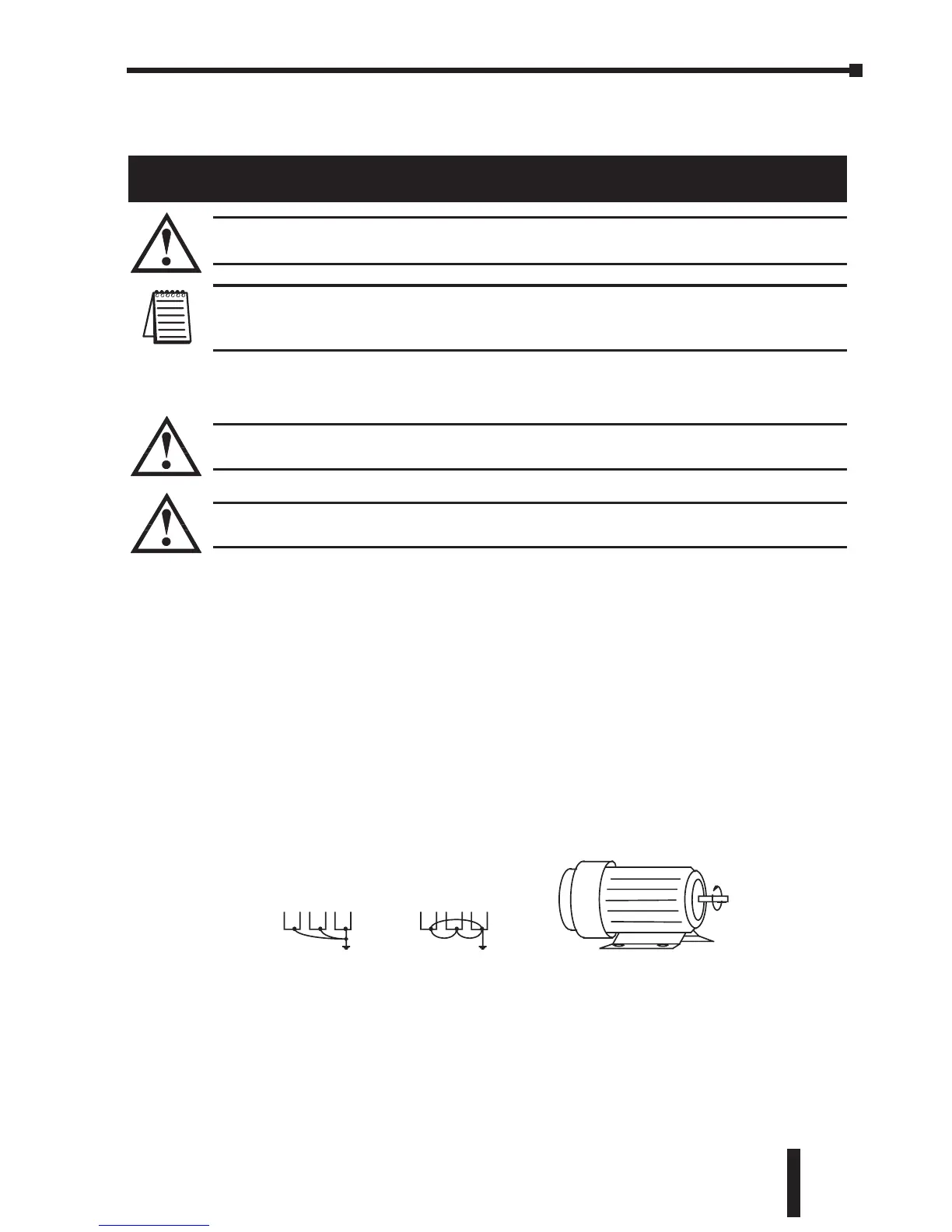
5. Multiple GS1 units can be installed in one location. All the units should be
grounded directly to a common ground terminal. The GS1 ground terminals
may also be connected in parallel, as shown in the figure below. Make sure
there are no ground loops.
6. When the AC drive output terminals T1, T2, and T3 are connected to the motor
terminals T1, T2, and T3, respectively, the motor will rotate counterclockwise
(as viewed from the shaft end of the motor) when a forward operation
command is received. To reverse the direction of motor rotation, switch the
connections of any of the two motor leads.
7. Make sure that the power source is capable of supplying the correct voltage
and required current to the AC drive.
 Loading...


