Chapter 5: GS1 MODBUS Communications
GS1 Series AC Drive User Manual
5–6
Communicating with Dir ectLOGIC PLCs
The following steps explain how to connect and communicate with the GS1
Series AC drives using DirectLOGIC PLCs.
Step 1: Choose the Appropriate CPU.
The GS1 Series AC drives will communicate with the following DirectLOGIC
CPUs using MODBUS communications.
• DL05 • DL06 • DL250
• DL260 • DL350 • DL450
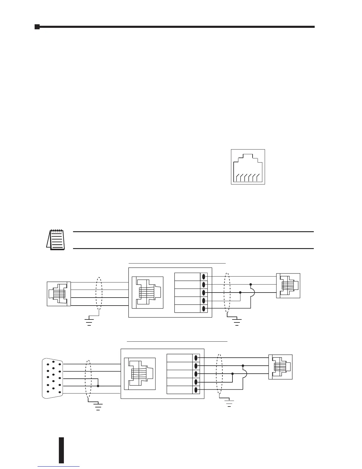
Step 2: Make the Connections
The GS1 Comm Port can accommodate an RS 485
network connection. The GS1 Comm Port pin-out
can be found to the right.
An RS-485 network cable can span up to 1000
meters (4000 feet). However, most DirectLOGIC
PLCs require an FA-ISONET (RS 232C to RS422/485 network adapter) in order to
make this type of connection.
Use the following wiring diagrams to connect your DirectLOGIC PLC to a GS1
Series AC drive with an RS-485 interface.
Note: If an FA-ISONET module is used in your connection, make sure the jumpers are
set for RS485 communications.
Continued on next page
 Loading...


