Step 4: Create a Project (cont’d)
Rung #1 (cont’d)
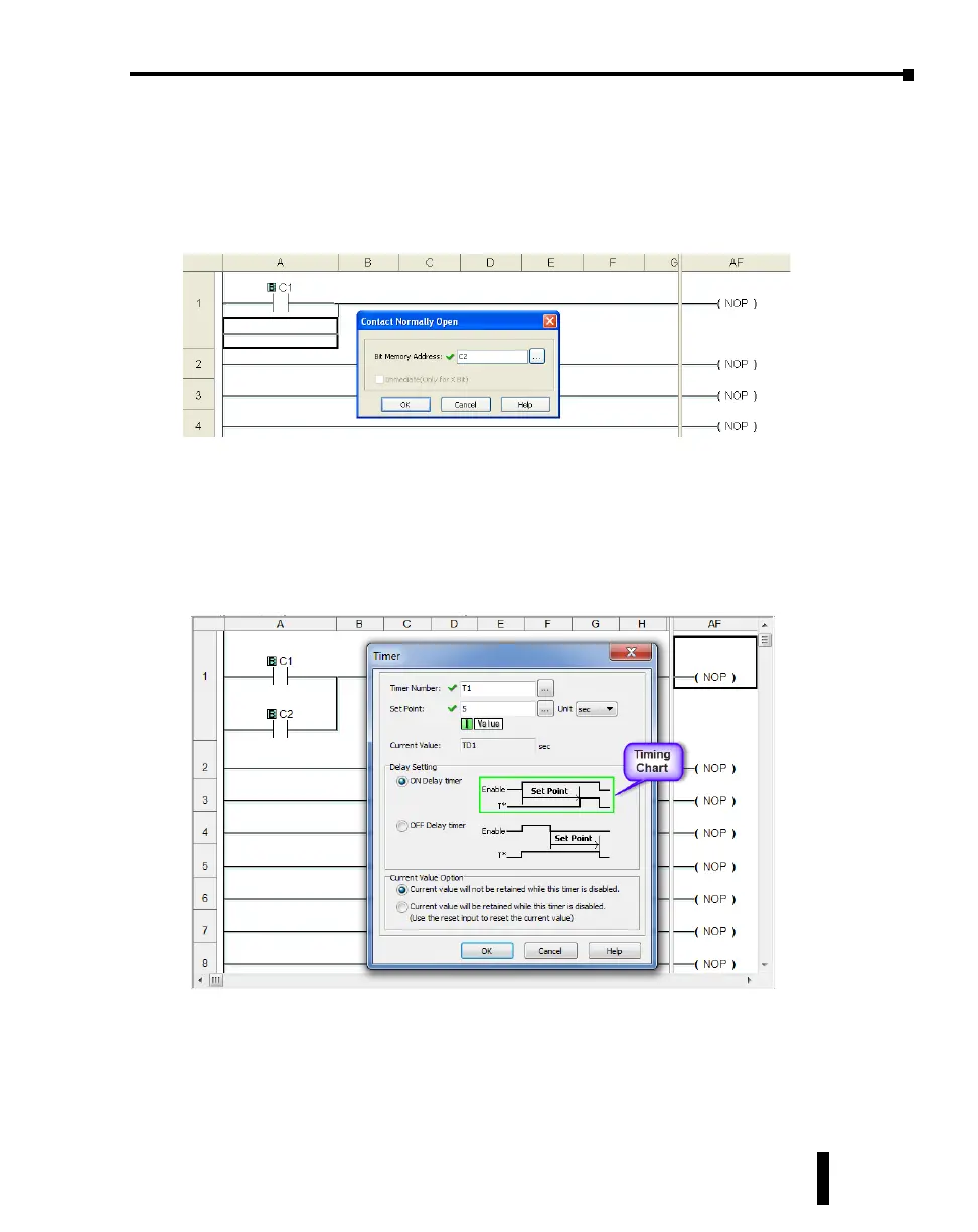
From the Instruction List, click & drag a Contact (NO) into the Box Cursor. Enter C2 into
the Bit Memory Address text box of the Contact Normally Open dialog box that pops up and
click OK. A normally open contact labeled C2 will be placed in parallel with the C1 contact.
Next, place the Box Cursor on the NOP coil at the far right of Rung #1. NOP stands for No
Operation and is a place holder in the ladder logic Coil Area. Click and drag a Timer from
the Instruction List into this location. Within the Timer dialog box, enter T1 into the Timer
Number text box, the value 5 into the Set Point, and select sec for the timing Unit. e Timer
dialog box shows a Timing Chart that graphically represents the function of the ON Delay
Timer, and also shows a selection for an alternative OFF Delay Timer mode of operation.
Leave the Delay Setting at ON Delay Timer and the Current Value Option set for the rst
selection. Click OK. A timer labeled T1 will be placed at the end of Rung #1.
Proceed to the next page to enter Rung #2.
CLICK PLUS PLC Hardware User Manual, 1st Edition, Rev. K – C2-USER-M
1-13
Chapter 1: Getting Started