Instructions, AutroFlame X33AF, 116-P-X33AF/IGB, rev. E, 2013-08-13, P/N 95-8625-17.1, Rev: 2/13
Autronica Fire and Security AS
Page 14
MAINTENANCE
IMPORTANT
Periodic flamepath inspections are not
recommended, since the product is not intended
to be serviced and provides proper ingress
protection to eliminate potential deterioration of the
amepaths.
WARNING
The sensor module (“front” half of the detector)
contains no user serviceable components
and should never be opened. The terminal
compartment is the only part of the enclosure that
should be opened by the user in the eld.
NOTE
Refer to the X33AF Safety Manual (116-P-X33AF-
SIL2/CGB) for specific requirements and
recommendations applicable to the proper
installation, operation, and maintenance of all SIL-
Certied X33AF ame detectors.
To maintain maximum sensitivity and false alarm
resistance, the viewing windows of the X33AF must be
kept relatively clean. Refer to the procedure below for
cleaning instructions.
CLEANING PROCEDURE
CAUTION
Disable any extinguishing equipment that is
connected to the unit to prevent unwanted
actuation.
To clean the windows and
o
i
plate, use Autronicas window
cleaner (part number 116-001680-001) and a soft cloth,
cotton swab or tissue and refer to the following procedure.
1. Disable any extinguishing equipment that is
connected to the unit.
2. Since the X33AF is less affected by contamination
than other detectors, removal of the oi plate is needed
only under extreme conditions. In addition, it is not
necessary to achieve perfect cleanliness, because
IR is not signicantly absorbed by slight lms of oil
and/or salt. If a fault condition is still indicated after
cleaning, remove and clean the oi Plate Removal and
Replacement procedure.
3. In all environments, clean all three viewing windows
and reector surfaces thoroughly. Use a cotton
swab and Autonicas window cleaning solution. Use
Isopropyl alcohol for contaminations that Autronicas
window cleaning solution can not remove.
IMPORTANT
When used in extreme environments, the reective
surface of the detector
o
i
plate may eventually
deteriorate, resulting in reoccurring
o
i
faults and
the need for
o
i
plate replacement.
o
i
PLATE REMOVAL AND REPLACEMENT
1. Disable any extinguishing equipment that is connected
to the unit.
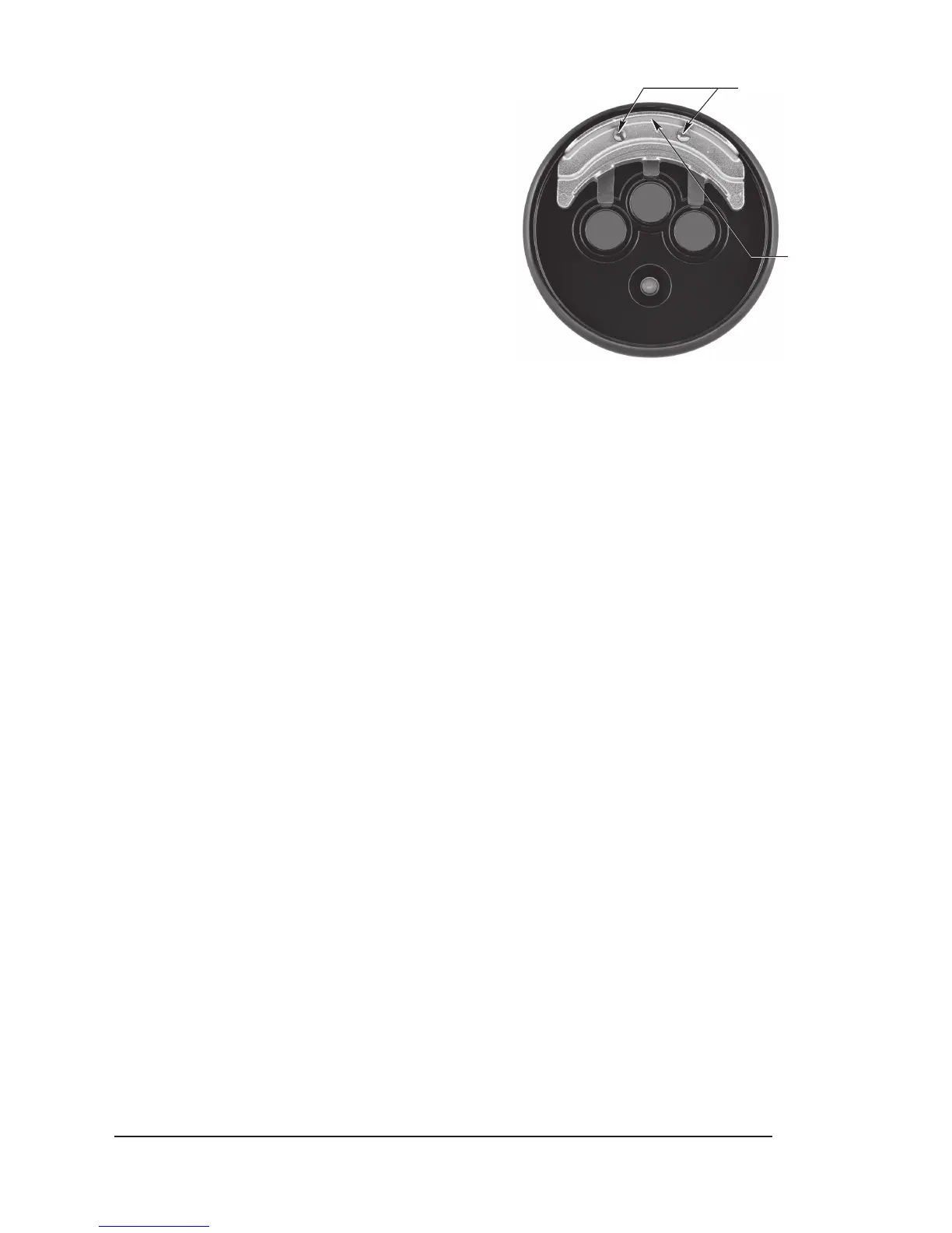
2. Loosen the two captive screws, then grasp the
o
i
plate by the visor and remove it from the detector.
See Figure 17.
3. Install the new (or cleaned)
o
i
plate.
NOTE
When installing the stainless steel plate, ensure
that the gasket is present and correctly seated to
prevent moisture or contaminants from penetrating
behind the plate. To ensure even seating, tighten
both screws equally.
4. Re-calibrate the detector's
o
i
system. Refer to the
Inspector Monitor manual (95-8581) for instructions
regarding
o
i
plate replacement and
o
i
system
recalibration.
CAUTION
Do not replace the
o
i
reector plate without also
recalibrating the
o
i
system.
Recalibration of the
o
i
system requires the use of
the Inspector Connector Cable and Inspector Monitor
Software. These two items are included in the
o
i
replacement kit, or they can be purchased separately. See
Ordering Information for details.
LOOSEN TWO CAPTIVE SCREWS
GRASP VISOR AND
REMOVE o
i
PLATE
B2106
Figure 17 –
o
i
plate removal
 Loading...