Instructions, AutroFlame X33AF, 116-P-X33AF/IGB, rev. E, 2013-08-13, P/N 95-8625-17.1, Rev: 2/13
Autronica Fire and Security AS
Page 2
The Auxiliary relay has normally open / normally closed
contacts, and is congurable for energized or de-energized
operation, and latching or non-latching operation.
0 to 20 mA Output
A 0 to 20 mA output is available as an option (in addition
to the three relays). This option provides a 0 to 20 mA dc
current output for transmitting detector status information
to other devices. The circuit can be wired in either an
isolated or non-isolated conguration and can drive a
maximum loop resistance of 500 ohms from 18 to 19.9
Vdc and 600 ohms from 20 to 30 Vdc. Table 1 indicates
the detector status conditions represented by the various
current levels. The output is calibrated at the factory, with
no need for eld calibration. A model with relays and
0-20 mA with HART is also available. Refer to Addendum
number 116-P-X33AFADDENDUM/YGB for complete
details.
NOTE
The output of the 0 to 20 mA current loop is not
monitored by the fault detection circuitry of the
X33AF. Therefore, an open circuit on the loop will
not cause the fault relay to change state or the
detector status LED to indicate a fault. The status of
the LED always follows the status of the relays.
An alarm condition will normally over-ride a fault condition,
unless the nature of the fault condition impairs the ability
of the detector to generate or maintain an alarm output,
i.e. loss of operating power.
LED
A tricolor LED on the detector faceplate indicates normal,
re alarm and fault conditions. Table 2 indicates the
condition of the LED for each status.
Table 2—Detector Status Indicator
OPICAL INTEGRITY (
o
i
)
Automatic
o
i
The X33AF includes the Automatic Optical Integrity
(
o
i
) feature — a calibrated performance test that is
automatically performed once per minute to verify
complete detector operation capabilities. No testing with an
external test lamp is required. The detector automatically
performs the same test that a maintenance person with a
test lamp would perform — once every minute, 60 times
per hour. However, a successful Automatic
o
i
test does
not produce an alarm condition.
The Protect•IR signals a fault condition when less than
half of the detection range remains. This is indicated by
the Fault output relay and is evident by the yellow color of
the LED on the face of the detector. The
o
i
fault condition
is self-clearing if the optical contamination is temporary. If
the contamination is not automatically cleared and the
o
i
fault remains, the detector may require cleaning or service.
See the "Troubleshooting" section for further information.
Magnetic
o
i
/ Manual
o
i
The detector also incorporates both Magnetic
o
i
(Mag
o
i
) and Manual
o
i
(Man
o
i
) features that provide the
same calibrated test as the Automatic
o
i
, and in addition
actuates the Alarm output to verify operation for preventive
maintenance requirements. These features can be
performed at any time and eliminate the need for testing
with a non-calibrated external test lamp.
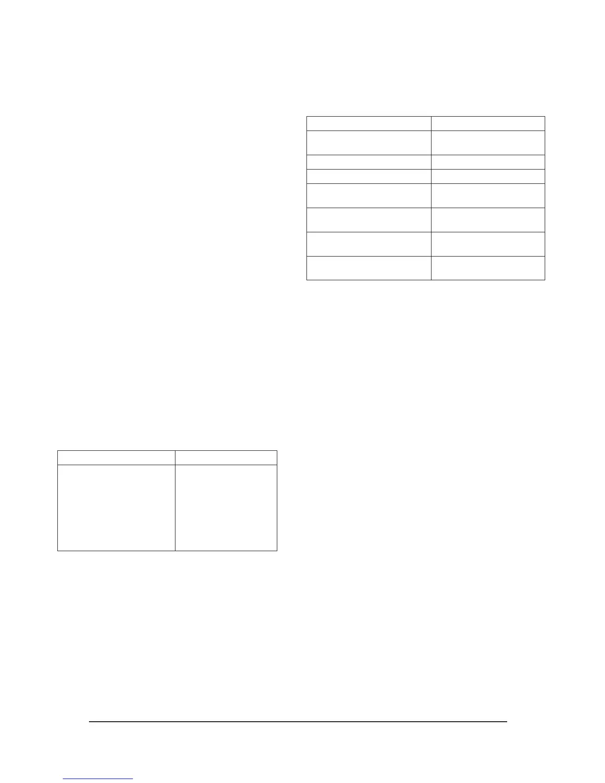
Table 1—Detector Status Conditions Indicated by Current Level
Current Level (±0.3 mA) Detector Status
0 mA Power Fault
1 mA General Fault
2 mA Oi Fault
3 mA Hi Background IR Fault
4 mA Normal Operation
20 mA Fire Alarm
Detector Status LED Indicator
Power On/Normal Operation
(no fault or re alarm)
Green
Fault Yellow
Fire (Alarm) Red
Low Sensitivity
One Yellow Flash
During Power-up
T- Low Sensitivity
Three Yellow Flashes
During Power-up
Medium Sensitivity
Two Yellow Flashes
During Power-up
Very High Sensitivity
Four Yellow Flashes
During Power-up
NOTE: See "Detector Sensitivity Levels" for additional information.
 Loading...