Trigger Interface
Interfacing the SM4 with your particular trigger system may be fairly straightforward or it
may be complicated. The variety of trigger designs available is the primary source of
complication. This appendix contains a lot of useful information about the different
approaches to trigger design and is essential information to anyone installing the SM4.
The Input Trigger
The SM4 is designed to trigger from either a square wave signal that varies from a low
(zero) volt to a (high) voltage between 6 and 15 volt. It may also use magnetic inductive
signal in conjunction with the internal reluctor adapter. A reluctor adapter converts the
sine like wave signal from the magnetic trigger to a square wave signal. The actual
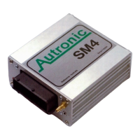
voltage of this voltage is not important because it is from low-to-high or high-to-low that is
used to trigger the SM4. This transition is referred to as the Trigger Edge for cylinder
pulse or reference pulse. This is shown in the following illustration as an upward or
downward facing arrow. An upward arrow would indicate that the trigger edge is the
transition from low-to-high and is called rising edge. If the trigger edge is the transition
from high-to-low, it will be shown as a downward facing arrow, and called falling edge.
For the SM4 to operate correctly a trigger edge must be generated. This trigger edge
must occur a fixed number of degrees before top dead centre (BTDC) and must not
change during different rpm’s. The position of the trigger is given in crankshaft degrees
and is called “Crank I/P Lead” in menu “I/P Crank & Cyl”. In Addition there should not be
any variation in the trigger angle between cylinders. The SM4 can be set to have any
trigger angle between 0-720 degrees.
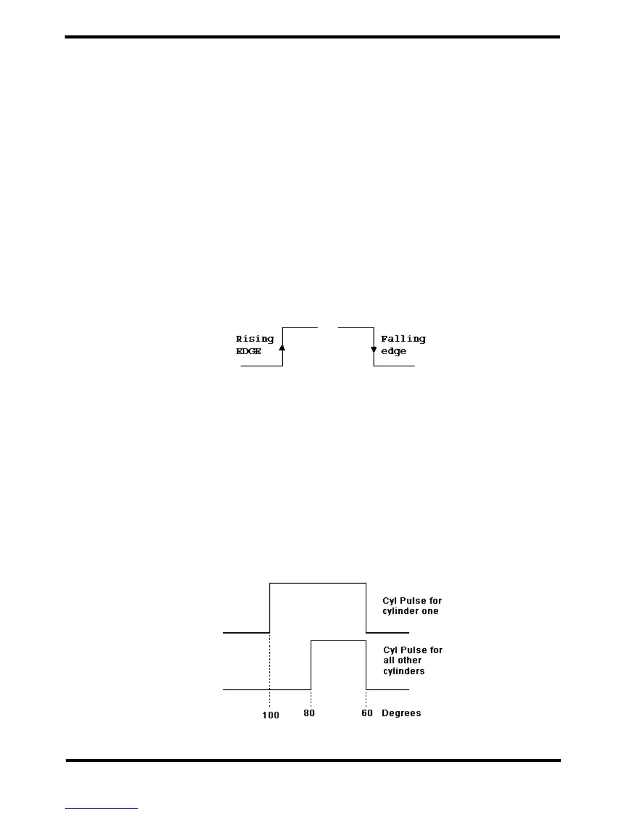
In some trigger devices the pulse given for cylinder one would be a different width than
pulse for all other cylinders. If the first edge, rising edge in this example were used as the
trigger edge than there would be a variation of 20º between the trigger for cylinder one
and all other cylinders. This would lead to cylinder one being 20º more advanced than all
other cylinders; also the input rpm would not be stable. The solution is use the trigger
point that is falling edge and to have the trigger angle “Crank I/P Lead” set to 60.
 Loading...