AUX DC Inverter Free Match 50HZ R32
Part6 Electrical Principle Diagram
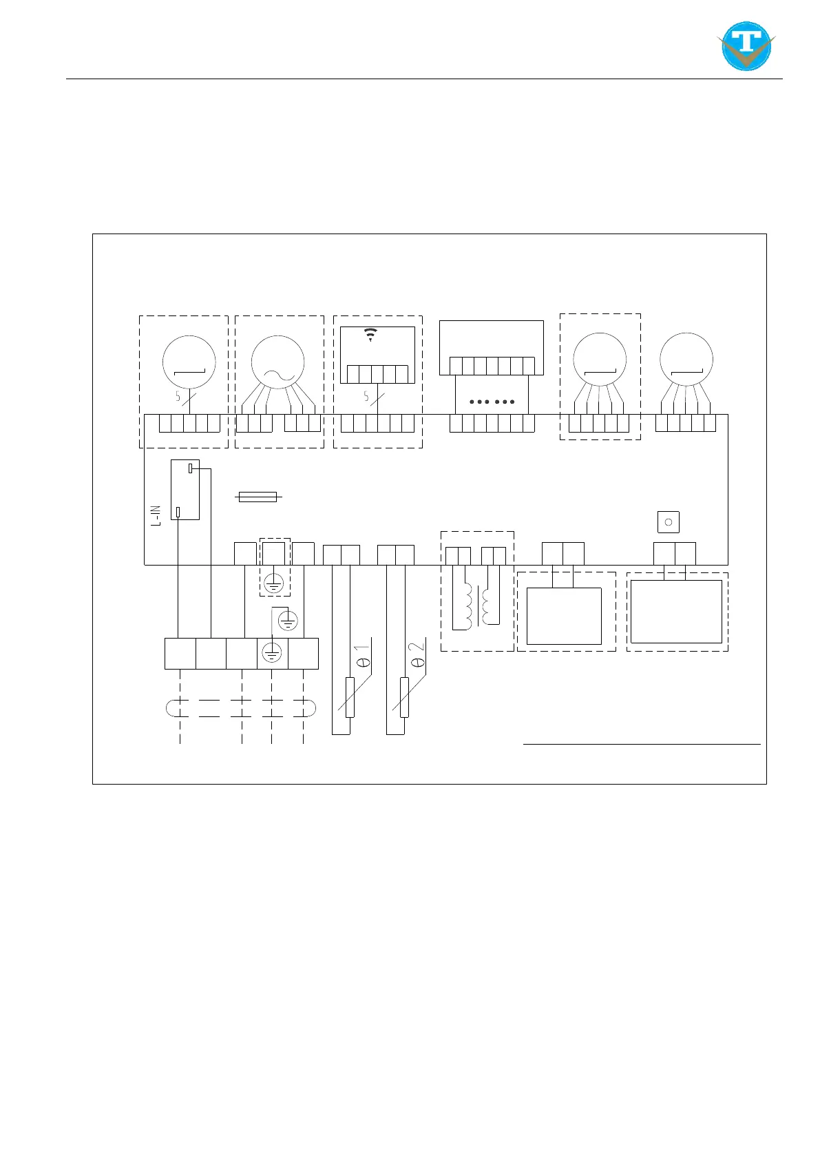
1. Wall Mounted
1.1 L Type (07K,09K,12K,18K)
NOTE: "Lo" on the terminal block does not need to be connected.
Dotted line part in the frame may not be used.
DC Fan Motor
AC Fan Motor
WIFI Module
Display receive panel
Step Motor
Step Motor
FUSE
3.15A 250V
PCB
Forced Switch
Transformer
Anion
High Voltage
Generator
Electrostatic
Duster
Temperature Sensor
To Outdoor Unit
Brow
L
N
PE
C
Red
Blue
Y/G
Black
L
L0
S
N
Some models have no content inside dashed frame
16437010000237
Indoor Unit Electric Chart
M1 M2
M4 M3
 Loading...