Page 60 - Linked DECT Systems
Page 60 DECT - Installation Manual
Introduction 38HBKD0001SAH – Issue 14 (27th October 2003)
Linked DECT Systems
Introduction
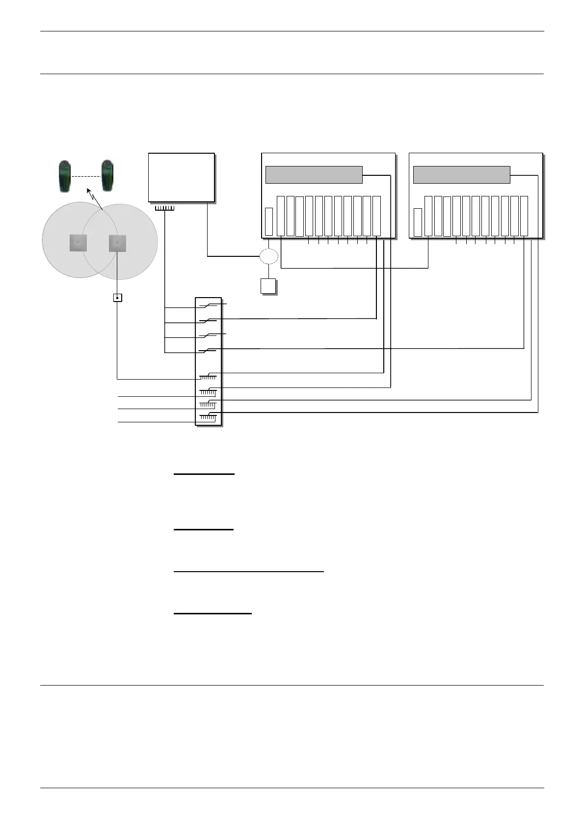
The DECT Link Kit allows two DCU's to be connected. They then act as a
single DECT system with one DCU taking the role of master and the other
slave.
Channels 8 - 15
Channels 0 - 7
Channels 24 - 31
Channels 16 - 23
Channels 40 - 47
Channels 32 - 39
Channels 56 - 63
Channels 48 - 55
DECT Expansion Board
Communi cat ions
Platform
PBX
MD
DECT Analogue Interface Cable
(25-Way Female D-Types to MDF)
5m 1
-Pair Cable to 25-Way Female D-Type for Channels 0 - 7
5m 12-Pair Cable to 25-Way Male D-Type for Base Stations 0 -7
IKm Single Twisted Pair Cable
Twisted Pair
nalogu
Interface
Cables
Serial Programming Cabl
Ser i al Port
DECT Intergratio
Cable
Either
PC
DECT Control Unit (Master)
5m 12-Pair Cable to 25-Way Male D-Type for Base Stations 8 - 15
To/From Base Stations 8 - 15
Link Car
Slot
Not Used
To/From DECT Analogue Interface Channels 8-63
Channels 8 - 15
Channels 0 - 7
Channels 24 - 31
Channels 16 - 23
Channels 40 - 47
Channels 32 - 39
Channels 56 - 63
Channels 48 - 55
DECT Expansion Board
DECT Analogue Interface Cables
(25-Way Female D-Types to MDF)
Serial Port
DECT Control Unit (Slave)
5m 12-Pair Cable to 25-Way Male D-Type for Base Stations 16 - 23
5m 12-Pair Cable to 25-Way Male D-Type for Base Stations 24 - 31
To/From Base Stations 16 - 23
To/From Base Stations 24 - 31
5m 1
-Pair Cable to 25-Way Female
-Type for Channels 64 - 71
To/From DECT Analogue Interface Channels 72 - 127
To/From Base Stations 0 -7
1m Link Cable
Not Used
Link Card Slot
Not Use
Not Used
Handsets
64 off max.
Slave Jack
Socket
Base Station
(16 off max.)
Repeater
The Link Kit consists of:
– Link Cards:
These cards (one slave and one master) go into the left hand slots of
each DCU motherboard. They provide an external connector for the
DECT Link cable.
– Link Cable
:
This cable connects between the two Link Cards. It is a 1m cable with
male connector and one end and female connector at the other.
– Replacement Eprom Chips:
If either cabinet contains an 13298200 chip, it must be replaced with
one of the 13298201 chips supplied in the Link Kit.
– Software Disk
:
This disk includes version 5 SIO and associated files which are
required for Linked DECT systems. It also includes new versions of
F_APP_DB.DAT. It also includes a FLASH.KTB file for upgrading
linked cabinets.
Upgrading Existing DECT Systems
Link Cards can only be used in DCU's with HW PCS6+, SW PCS5+. If
necessary the motherboard of any existing DCU must be upgraded to that
level (by either replacing the motherboard or the whole DCU).
The Link Kit includes replacement Eprom chip to be used if necessary
(see Eprom Replacement on page 63).