Wireless Fixed Base
Issue 6 September 2001
3-15
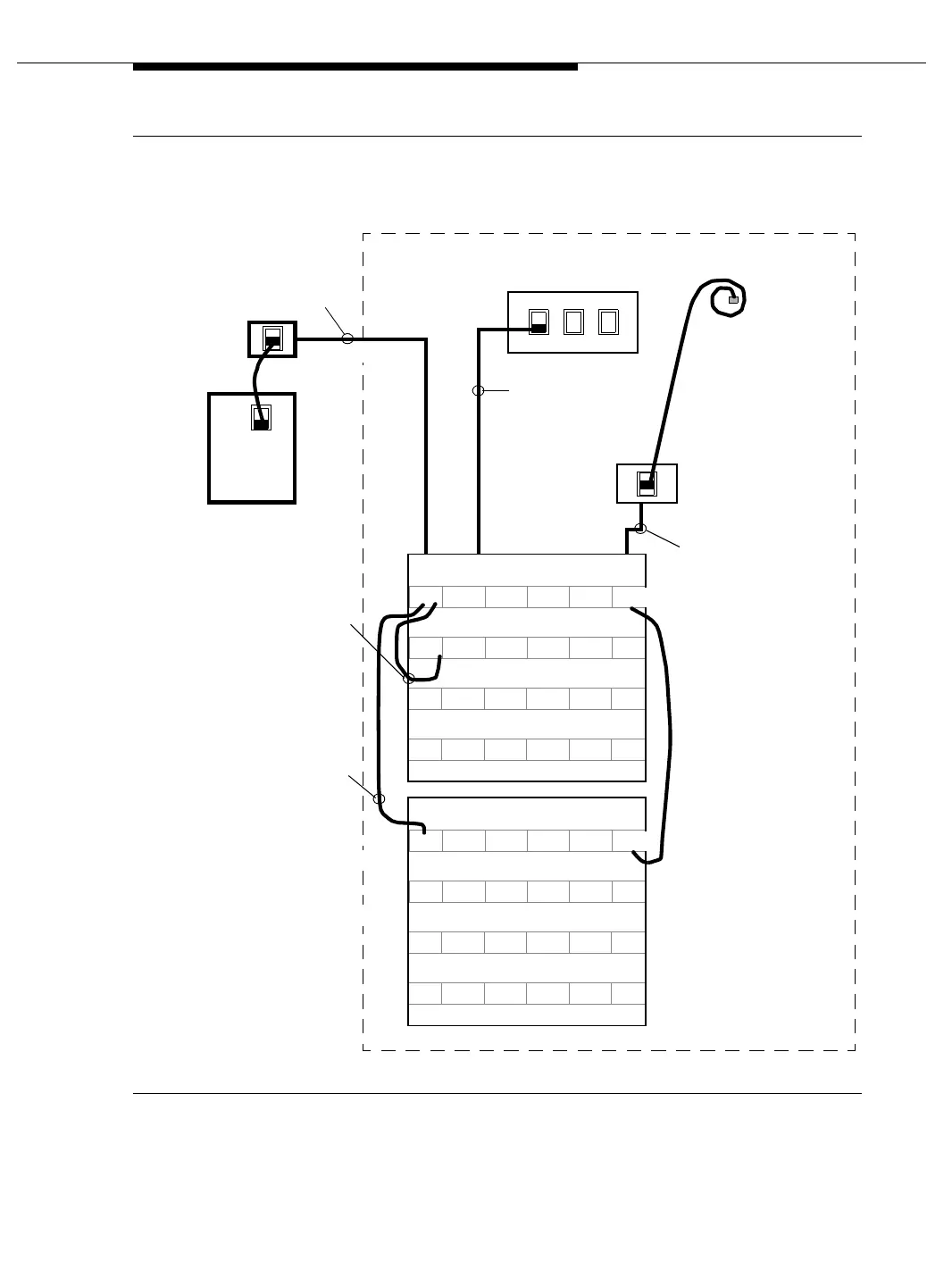
Figure 3-3. Typical Terminations and Cross-Connects for WFBs
PHONE LINE
OTHER
Transformer (4) Each
DW8A-DE Cord
Coiled
Four Pairs to WFB
1A 1B 2A 2B
To Firmware
103 Jack
DW8A-SE Cords
TX1 TX2 TX3 TX4
WFB Ports
1A 1B
Firmware
Port
2A 2B
Located Inside Equipment Room
Place the dual jumper from the
From the transformer DW8A
WFB
“A1”
4-pair cable routed from
DW8A-DE
Block
Cord
110 hardware located in
equipment room to
103 connecting block
next to WFB.
DW8A-SE Cord
103848800 terminates
all pairs on the 110
station hardware.
Firmware
103 Connecting Block
4-Pair Cable
Place the 3-pair
jumper from the
firmware port to
the 4-pair cable
serving jack.
103 Connecting
cord jumper, connect the W/BR
(ground) pair to the W/BL-BL/W
pair of the 4-pair cable to the
WFB. Also connect the BR/W
(-48V) pair to the W/BR-BR/W
pair of the 4-pair cable to the
WFB. Doubling up the pairs
extends the power from the
power supply to the WFB
to 795 ft.
WFB radio card port to the
W/O-O/W and W/G-G/W pairs of
the 4-pair cable to the WFB.
Radio
Card “A”
Radio
Card “B”
110AC2-600 Switch Port Hardware
Avaya switch tech will
install this 103 jack.
110AB2-300 Station
Hardware
(See the following
“103 Connecting Block”
figure.)
NOTE: See the following
“Cross-Connects
for WFBs” figure.