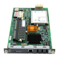
Job Aid: Replacing the S8300 Server or its hard drive
14 Job Aids for Field Replacements (FRUs) for the Avaya S8300 Server with the G700 Media Gateway
f. S8300B: Detach the hard-drive ribbon cable from the hard drive (leave cable attached to
the S8300 Server).
g. S8300B: Unpack and install the new hard drive on the S8300. Standoffs for the new hard
drive should be included in the new hard drive package.
Note: If standoffs are not included with the new hard drive, remove the standoffs from
the old drive and reuse them. Before screwing the standoffs into the new
hard drive, clean the threads thoroughly with a damp cloth or paper towel.
h. S8300B: Screw the standoffs into the new hard drive.
CAUTION: In Step i, be careful not to bend the pins on the hard drive. Leave the four jumper
pins to the right of the ribbon cable open and unconnected, as shown in
Figure 1: S8300B hard drive replacement
on page 13.
i. S8300B: Connect the open end of the hard-drive ribbon cable (which is attached to the
S8300 Server) to the replacement hard drive, as shown in Figure 1: S8300B hard drive
replacement on page 13. Connect pin number one to the end of the ribbon connector
marked with the red stripe.
j. S8300B: Place the hard drive on the S8300 Server with the standoffs aligned with the
screw holes.
k. S8300B: Hold the S8300 Server on its side, with the hard drive in place, and screw the
four screws through the bottom of the S8300 Server into the hard-drive standoffs.
l. S8300B: Insert the S8300 into the appropriate slot of the media gateway, but do not
completely insert the server in the slot.
For example, slot V1 of the G700. The LED panel (above slot V1) must be removed and
reinserted together with the S8300 Server. Insert both the LED panel and S8300 Server
about one-third (1/3) of the way into the guides (the guides are in slot V1 for the S8300
and above slot V1 for the LED panel). Push both the modules (together) back into the
guides, gently and firmly, until the front of each module aligns with the front of the G700.
Important: Step m through Step t apply to the S8300C or S8300D only.
m. S8300C or S8300D: From the bottom of the S8300 Server remove the two screws that
attach to the hard-drive standoffs (Refer to Figure 2: S8300C hard drive replacement
on
page 15).

 Loading...