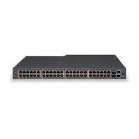
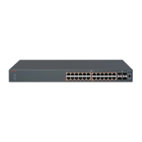
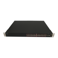
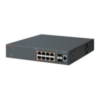
Table 6: PWR+ RJ-45 connector pin assignments
Connector Pin Number Signal Description
1 RX+/power– Receive Data+/power–
2 RX–/power– Receive Data–/power–
3 TX+/power+ Transmit Data+/power+
4 Not applicable Not applicable
5 Not applicable Not applicable
6 TX–/power+ Transmit Data–/power+
7 Not applicable Not applicable
8 Not applicable Not applicable
Important:
The Avaya VSP 4000 PWR+ models use pins 1, 2, 3, and 6 for PoE+, and is compliant with
Type 2 (MDI-X) in IEEE802.3at.
Console port pin assignments
The following table describes the console port pin assignments in the Avaya VSP 4000.
Important:
Avaya VSP 4000 supports only CLI Quickstart use on the console port.
Table 7: DB–9 Console port pin assignments
Connector Pin Number Signal
1 Carrier detect (not used)
2 Transmit Data (TXD)
3 Receive Data (RXD)
4 Data terminal ready (not used)
5 Signal ground (GND)
6 Not used
7 Request to send (not used)
8 Not used
9 Ring indicator (not used)
Installing the Avaya VSP 4000 4850GTS Series
May 2016 Installing Avaya Virtual Services Platform 4850GTS Series 28
Comments on this document? infodev@avaya.com

 Loading...


