3
Installation
Getting Familiar With the AVer EVC130P
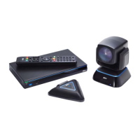
EVC includes Main System, MIC, Camera and Remote Controller.
MAIN SYSTEM
Front Panel:
Name Function
(1) LED Indicator Show you the status of your LAN connection.
Solid Green:
LAN connection is successfully
Flash Green:
Data transmission is processing through the LAN
connection.
(2) POWER Button Press this button to turn on/off main system. Red: power off; Blue: power
on
(3) USB Port Use to connect the USB storage for system log saving and FW upgrade.
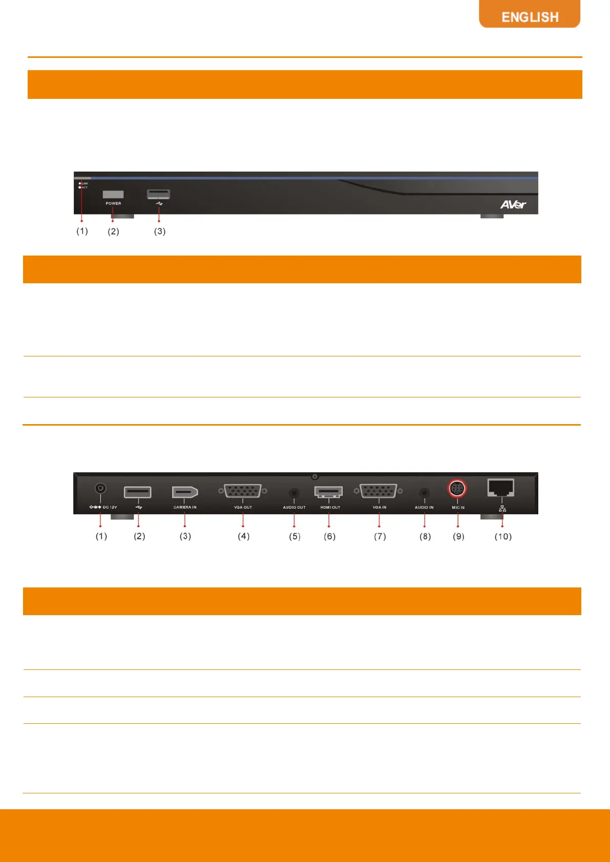
Back Panel:
Name Function
(1) POWER Port
Connect the power supply cord and adapter to the power port located on
the back panel. And connect the other end of the power cord to a
suitable power outlet.
(2) USB Port This port is the same as USB Port located on the front panel.
(3) CAMERA IN Port Connect the camera to the main system via a camera cable.
(4) VGA OUT Port
Connect the VGA cable to the VGA OUT port located on the back panel,
and connect the other end of VGA cable to a display device to output
video signal. In dual screen configuration, the output screen connected
to this port will be set up to secondary screen automatically.