XR Series Installation and Technical Instructions 25
3.2 Wiring the XR 2000
Communication Wiring All communications wiring terminates at the controller board.
Communications should be wired before applying power to the unit.
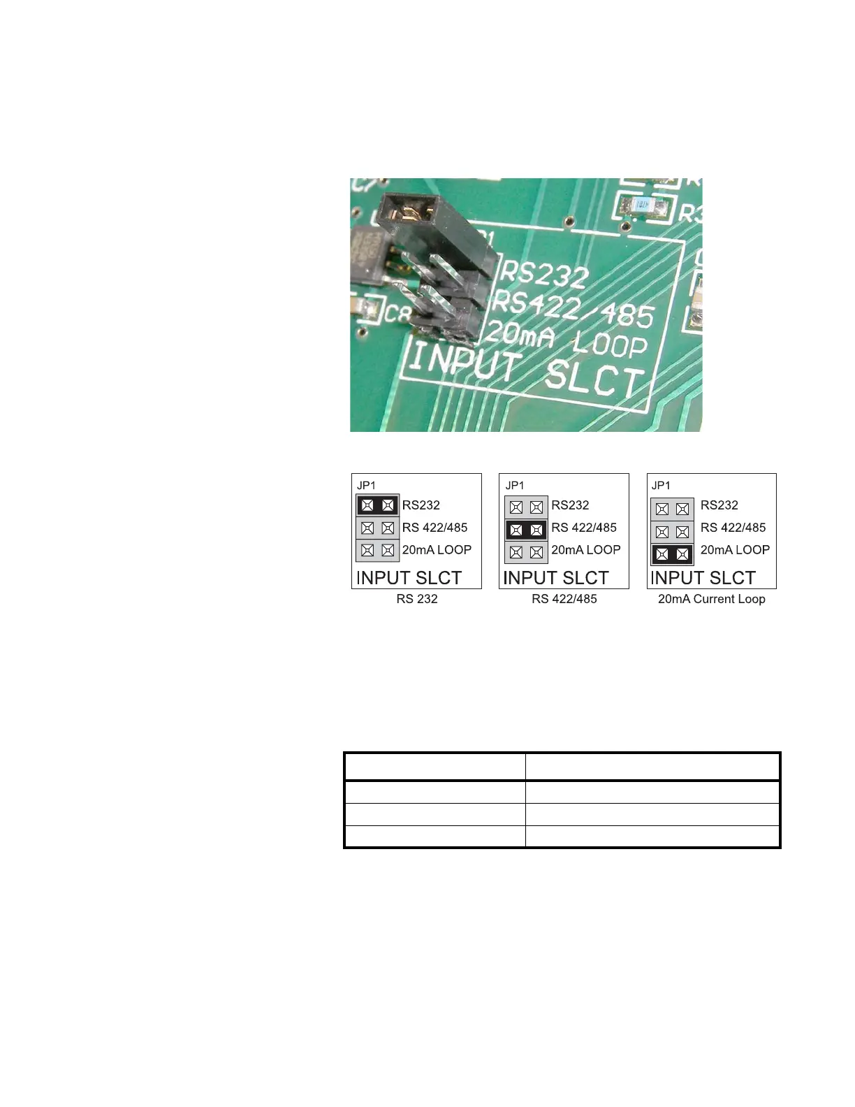
Communication Input Jumper A communications input type (RS 232, RS 422/485, or 20 mA Loop) must be
selected by placing the jumper on the appropriate pins. See Figure 3.8.
Figure 3.8 Jumper positions
RS 232 Wiring
1. Set the Communication Input Jumper (JP 1) to RS232.
2. Terminate the indicator’s communication wires at the RS 232 terminal
(J3). See table below:
INDICATOR TO XR
TRANSMIT (TX) RECEIVE (RX)
RECEIVE (RX) NO CONNECTION
SIGNAL GROUND (GND) SIGNAL GROUND (SIG GND)
 Loading...