Pro Tools | HD I/O Guide8
Analog Input
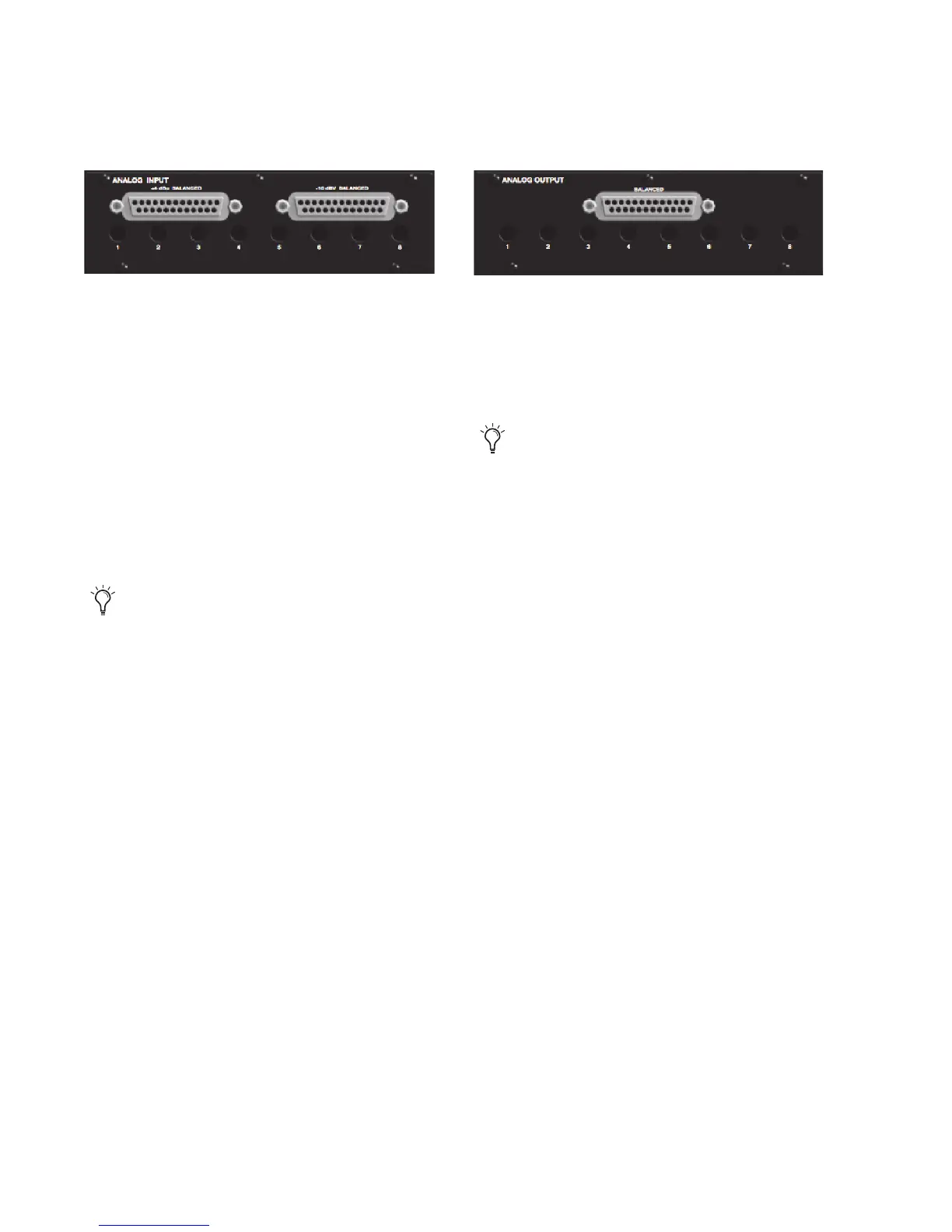
The HD I/O Analog In card contains connectors
for analog audio input with 24-bit, 192 kHz A/D
converters. Input is provided through two discrete
DB–25 connectors (one for +4 dBu sources, and
the other for –10 dBV sources). You can connect
sources at both operating levels and choose be-
tween them from within Pro Tools.
+4 dBu Balanced
Provides eight balanced input
channels at +4 dBu nominal operating levels.
–10 dBV Balanced
Provides eight balanced input
channels at –10 dBV nominal operating levels.
For wiring information, see Chapter 6, “Pinout Di-
agrams for the DB-25 Connectors.”
For each channel, you can select input level from
within the Hardware Setup dialog (see “Hardware
Setup” on page 21).
Input Trims
The Input Trims below the DB–25 connectors are
used to individually calibrate each channel’s input
level. See “Input Trims” on page 30.
Additionally, the Limiter function helps avoid dig-
ital clipping (see“Limiter” on page 26).
Analog Output
The HD I/O Analog Out card contains a single
DB–25 connector and Output Trims for eight
channels of analog audio output. These balanced
outputs operate at +4 dBu levels. See Chapter 6,
“Pinout Diagrams for the DB-25 Connectors.”
Output Trims
The Output Trims below the DB–25 connector are
used to individually calibrate each channel’s out-
put level. For more information, see Chapter 7,
“HD I/O Calibration Mode Instructions.”
Most consumer electronics operate at –10 dBV
levels, and may not feature balanced inputs and
outputs. You can connect –10 dBV signals to
the –10 dBV inputs, but you will need to make
sure that the negative terminals are not con-
nected.
For –10 dBV gear, you can switch a jumper
on Analog Output cards (on a channel-by-
channel basis) from the default Hi position
to Lo for a –6 dB pad. You can then adjust
the Trim pot for the corresponding output
channels by an additional –4 dB to accom-
modate –10 dBV gear. For more informa-
tion, see Chapter 7, “HD I/O Calibration
Mode Instructions.”