1. Make sure the safety lanyard is connected to the camera.
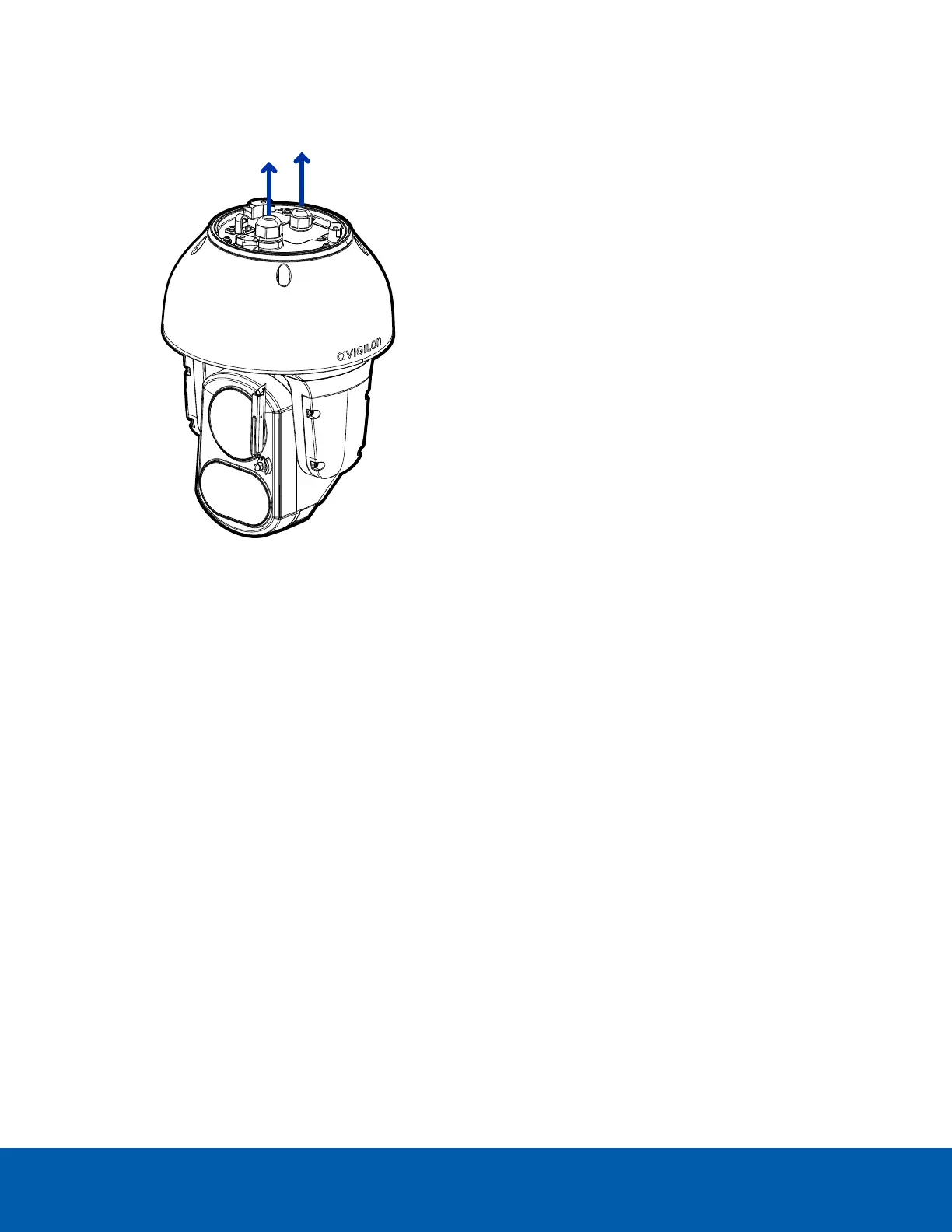
2. Remove the sealing gland caps from the top of the camera.
3. If there are external input or output devices that need to be connected to the camera (for example:
door contacts, relays, analog video, speakers, etc.), connect the devices to the camera I/O connector
cable.
4. Connect power using one of the following methods:
l
IEEE 802.3bt compliant Class 8 (90W) PoE Injector (POE-INJ-BT-90W-NA) — Connect an
Ethernet network cable to the injector.
l
External Power — Connect a 24V DC or 24V AC (RMS) auxiliary power source that supports up
to 75 W or 110VA.
For more information, see ConnectingtoPowerandExternalDeviceson page19.
5. Thread the Ethernet cable into the cable gland.
a. The cable gland for the Ethernet cable already has an opening for the cable along the side of
the gland.
Do not cut or slice the cable gland. This may make it possible for water to enter the camera, and
could void the warranty.
b. Push the cable through the gland cap, and then the opening on the side of the cable gland.
Ensure the orientation of the cable and cable gland matches the following image.
Connecting Cables 11
 Loading...