Connecting to Power and External Devices
CAUTION — Be careful to only connect power to the Auxiliary Power Wires or the camera will be
damaged.
If PoE is not available, the camera may be powered through the auxiliary power cable using either 24V DC or
24V AC. The power consumption information is listed in the product specifications.
To power the camera, connect the two power wires to the red and black auxiliary power wires. The
connection can be made with either polarity.
WARNING — This product is intended to be powered by a UL Listed Power Unit marked “Class 2” or
“LPS” or “Limited Power Source” with output rated 24 V AC +/- 10%, 110 VA min. or 24 V DC +/- 10%,
75W min.
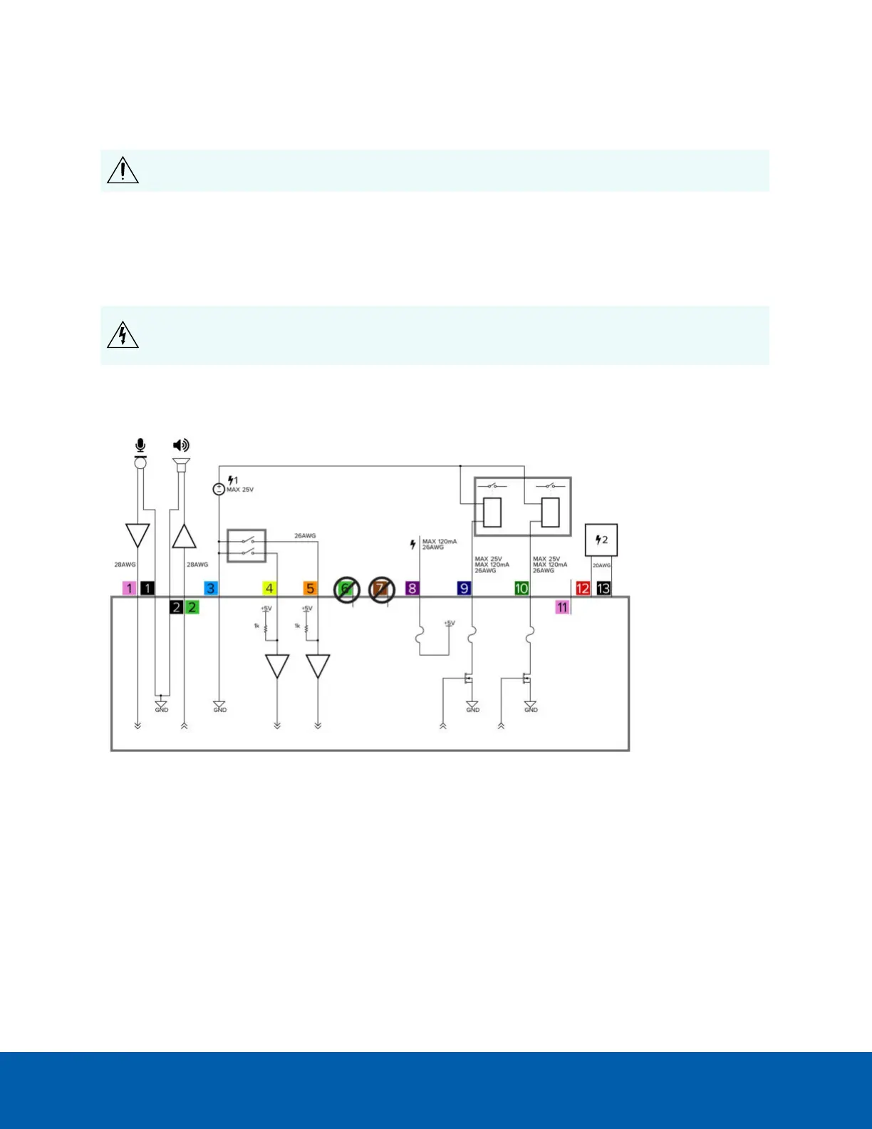
Power supplies and external devices are connected to the camera through the power and I/O wires. The
pinout for the I/O and power wires is shown in the following diagram:
Figure 7: Example application.
1. Pink (AUDIO_IN) — Audio Input (line level)
An external power amplifier should be used when connecting speakers and microphones, as shown in
the diagram.
a. Black — Audio Ground
2. Light Green (AUDIO_OUT)— Audio Output (line level)
b. Black — Audio Ground
3. Light Blue (GND) — Ground for digital inputs and outputs.
Connecting to Power and External Devices 19
 Loading...