Operating Manual for Controller VIBTRONIC
®
SC(E)…-2
©2002 AViTEQ Vibrationstechnik GmbH Version 02/2003 4–5
4
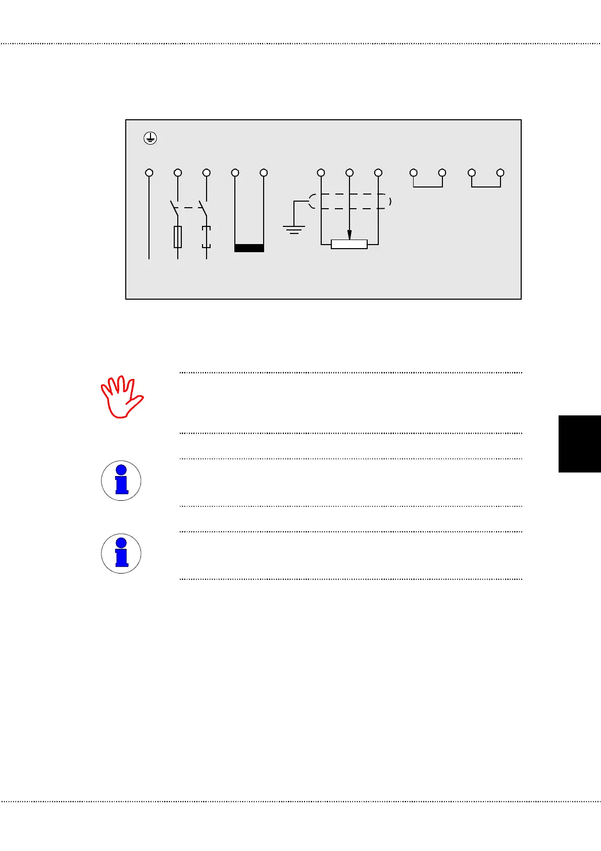
Make certain that the fuse protection is in accordance with connection diagram.
Install at least one fuse – but in any case, F1 in accordance with connection dia-
gram Figure 4.9 – as a super-fast-acting safety fuse for safeguarding the thyristor
in the controller.
Use only a potentiometer (limit value 1 kOhm) with linear characteristics for the
vibration-width adjuster. Shield the signal lines to guarantee electromagnetic com-
patibility if the lines exceed five metres in length!
For magnetic vibrator operation without external release circuit, terminals 12 and
13 must be connected by a wire bridge. If the bridge is missing, the vibrator volt-
age at terminals 3 and 4 is zero; the magnetic vibrator does not function.
1234 567 1213
PE L1 L2(N)
Magnetic
vibrator
Potentiometer
1 kOhm (linear)
Bridge
0
Figure 4.3 Standard terminal assignment with mains input (terminals PE, 1 and 2),
magnetic vibrator (terminals 3 and 4) and vibration-width adjuster
(terminals 5, 6 and 7)
PE
17 18
Bridge
NOTE
NOTE

 Loading...