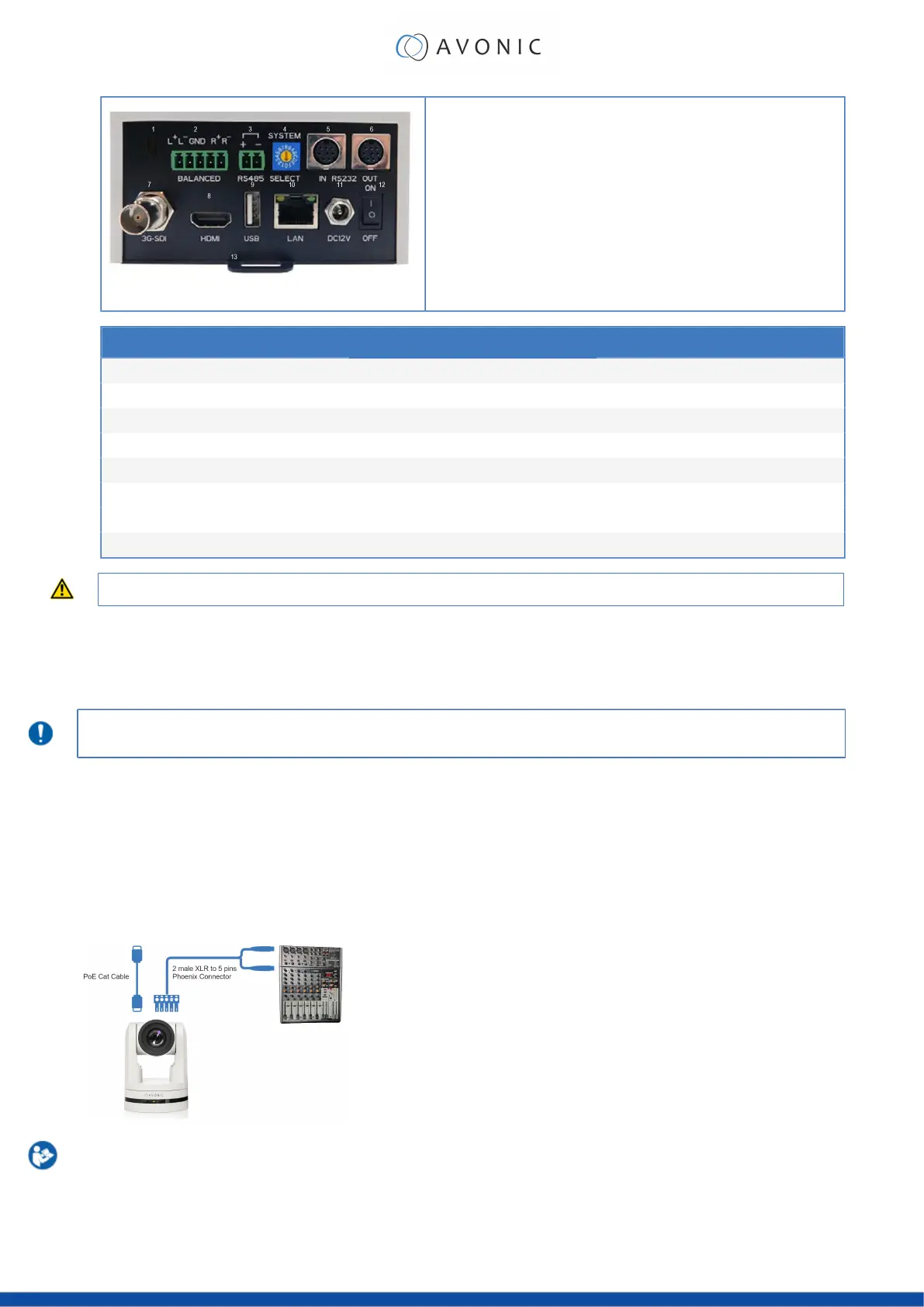
Figure 9: Camera Ports
1. Kensington Lock
2. Balanced Audio Line in 5-pin Phoenix connector
3. RS-485 two-wire serial communication with 2-pin Phoenix connector
4. System Select (see Using the System Select)
5. RS-232 mini-DIN-8 IN (connect the supplied RS-232 cable)
6. RS-232 mini-DIN-8 OUT for daisy chaining RS-232 connection
7. BNC 3G-SDI output, SMPTE 425M level A.
8. HDMI Type A
9. USB2.0 Type A, UVC video output and control
10. RJ45 Ethernet, with PoE (48Vdc, 0.25A, comply with LPS/PS2 circuits)
11. DC12V power with locking screw (connect the supplied DC PSU)
12.Power ON/OFF 13. Fall protection eye
Cable (average) cable length maximum cable length
RS-485 2 meter 1200 meter
RS-232 2 meter 10 meter
Balanced Audio 2 meter 100 meter
3G-SDI 2 meter 100 meter
HDMI 2 meter 15 meter
USB 2.0 2 meter 5 meter (A to A: 2 meter)
RJ45 Ethernet 2 meter undefined
DC12V power 2 meter fixed
If you use these cables for medical purposes, it is important that the maximum cable length must NEVER be exceeded.
2. If you have connected the power cable to the camera, set the power switch at the back of the camera to
the 'ON' position. If you use a PoE Ethernet connection, ensure that the Power switch is always ‘ON’.
The camera starts initializing by first rotating the Pan-Tilt to the maximum top right position and then to the
center after empowering.
If position preset '0' has been stored, this is the position that will be called after initialization.
The current IR-channel setting and IP Address of the camera are displayed on the OSD Menu. From this point
onwards, the user can start controlling the camera.
Balanced Audio Connection
To connect balanced audio to the camera, you need the following:
•
Double Male XLR cable to connect to a 5 pins phoenix connector (CTBP92HE/5: see package contents.).
•
Audio input device with multiple XLR input/ outputs, such as a mixer.
•
PoE (CAT) cable for streaming. See below:
Follow the instructions below to connect the audio cable to the phoenix and the XLR connectors.
1. Connect the wires of the audio cable as is shown in picture 1 to both XLR connectors. Note that the
pictures of the connector's back are mirrored!
2. Connect the wires of the other side of the audio cable as is shown in picture 2.
16
 Loading...