- 25 -
SW2 - ADDRESS OnE PA HP and OnE DT HP
Sensor DIP1DIP2DIP3DIP4DIP5 Sensor DIP1DIP2DIP3DIP4DIP5 Sensor DIP1DIP2DIP3DIP4DIP5
1
ON ON ON ON ON
12
OFF OFF ON OFF ON
23
ON OFF OFF ON OFF
2
OFF ON ON ON ON
13
ON ON OFF OFF ON
24
OFF OFF OFF ON OFF
3
ON OFF ON ON ON
14
OFF ON OFF OFF ON
25
ON ON ON OFF OFF
4
OFF OFF ON ON ON
15
ON OFF OFF OFF ON
26
OFF ON ON OFF OFF
5
ON ON OFF ON ON
16
OFF OFF OFF OFF ON
27
ON OFF ON OFF OFF
6
OFF ON OFF ON ON
17
ON ON ON ON OFF
28
OFF OFF ON OFF OFF
7
ON OFF OFF ON ON
18
OFF ON ON ON OFF
29
ON ON OFF OFF OFF
8
OFF OFF OFF ON ON
19
ON OFF ON ON OFF
30
OFF ON OFF OFF OFF
9
ON ON ON OFF ON
20
OFF OFF ON ON OFF
31
ON OFF OFF OFF OFF
10
OFF ON ON OFF ON
21
ON ON OFF ON OFF
32
OFF OFF OFF OFF OFF
11
ON OFF ON OFF ON
22
OFF ON OFF ON OFF
By DEFAULT, the sensors are supplied with DIP SWITCHES 1 to 5 set to OFF (sensor 32)
ON
1 2 3 4 5 6 7 8
ON
1 2 3 4 5 6 7 8
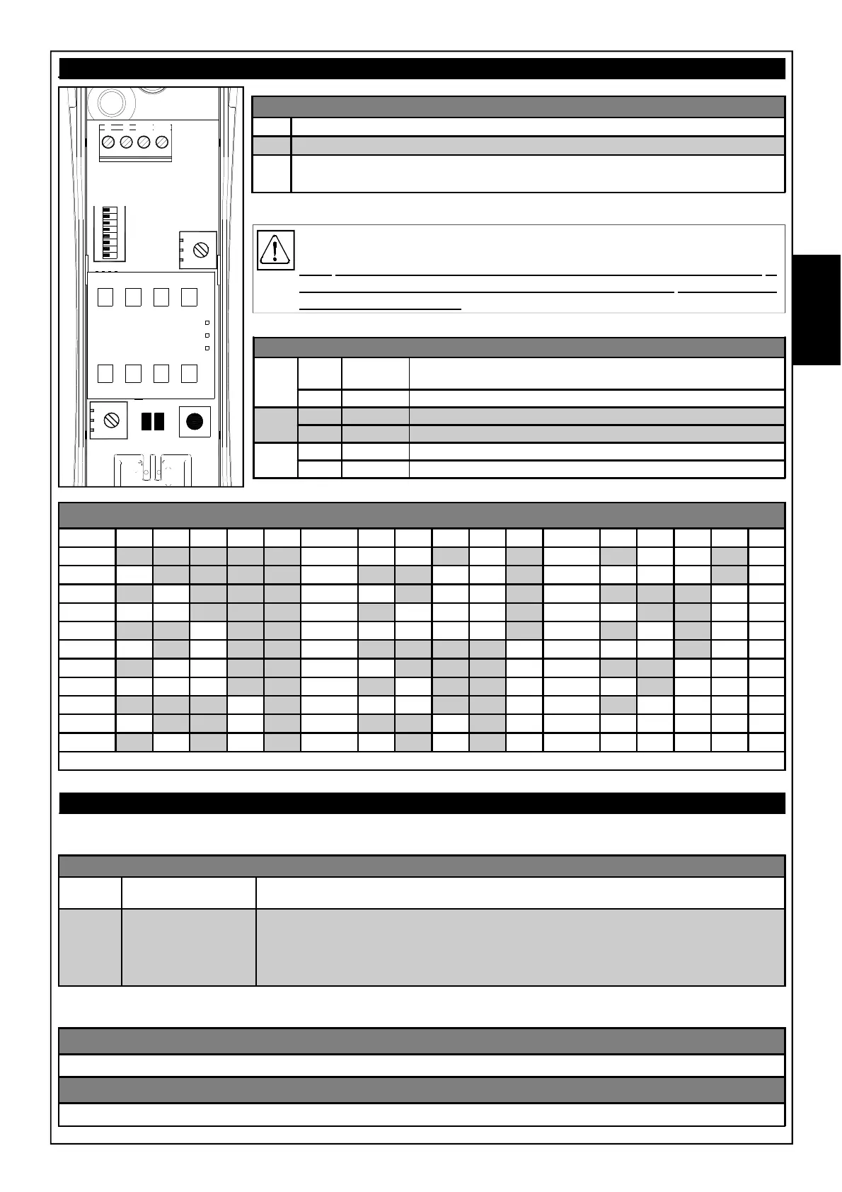
SW2
-
+
DADB
RV1
RV2
TAMPER
L1
L2
OnE PA HP and OnE DT HP
TERMINAL BLOCK
-
Negative power
+
12 V positive power =
DA
RS485 serial: For connection to the dedicated input of the satellite XSATHPs or
directly to the RS485 serial of the controllers prepared
DB
Exclusively for the connection of the DA and DB serial communication
terminals, we recommend shielded cables with a section of 0.5 mm² each,
while the section of the power cables (+ and -) of the equipment connected to
the serial port must be sized according to the type of system, according to the
experience of the installer.
Trimmer RV1 - Microwave range (Models One DT and OnE DT HP only)
Trimmer for adjusting the microwave range (turning it counterclockwise gives the minimum range).
Trimmer RV2 - Infrared range
Trimmer for adjusting the infrared range (turning it counterclockwise gives the minimum range).
Common configurations OnE PA, OnE DT, OnE PA HP e OnE DT HP
Depending on the setting of DIP6 of bank SW2, the yellow LED can indicate the status of the microwave or the
status of the anti-masking circuit.
In addition to trimmer RV1 for adjusting the microwave range, the sensor has a trimmer RV2 for adjusting the range
of the infrared
LED
BLUE
(LD1)
Flashes:
Steady on:
alternating with the yellow LED for about 60 seconds on first power-on
general alarm signal
YELLOW
(LD2)
DIP 6 of SW2 to OFF
DIP 6 of SW2 to ON
Flashes:
Steady on:
Fast flashing:
Slow flashing:
Steady on:
alternating with the blue LED for about 60 seconds on first power-on
Anti-masking signal
Anti-masking pre-alarm signal
Anti-masking calibration after closing the cover
Microwave alarm signal
SW2 - FUNCTIONS
DIP 6
ON
Yellow LED displays status of the Microwave (Model OnE DT HP
only)
OFF DEFAULT Yellow LED displays status of the Anti-mask
DIP 7
ON Anti-mask Active
OFF DEFAULT Anti-mask Disabled
DIP 8
ON
Tamper Accelerometer enabled
OFF DEFAULT
Tamper Accelerometer excluded
E
N
G