AXIS 221/223M Installation Guide Page 5
ENGLISH
10 pin I/O terminal connector block
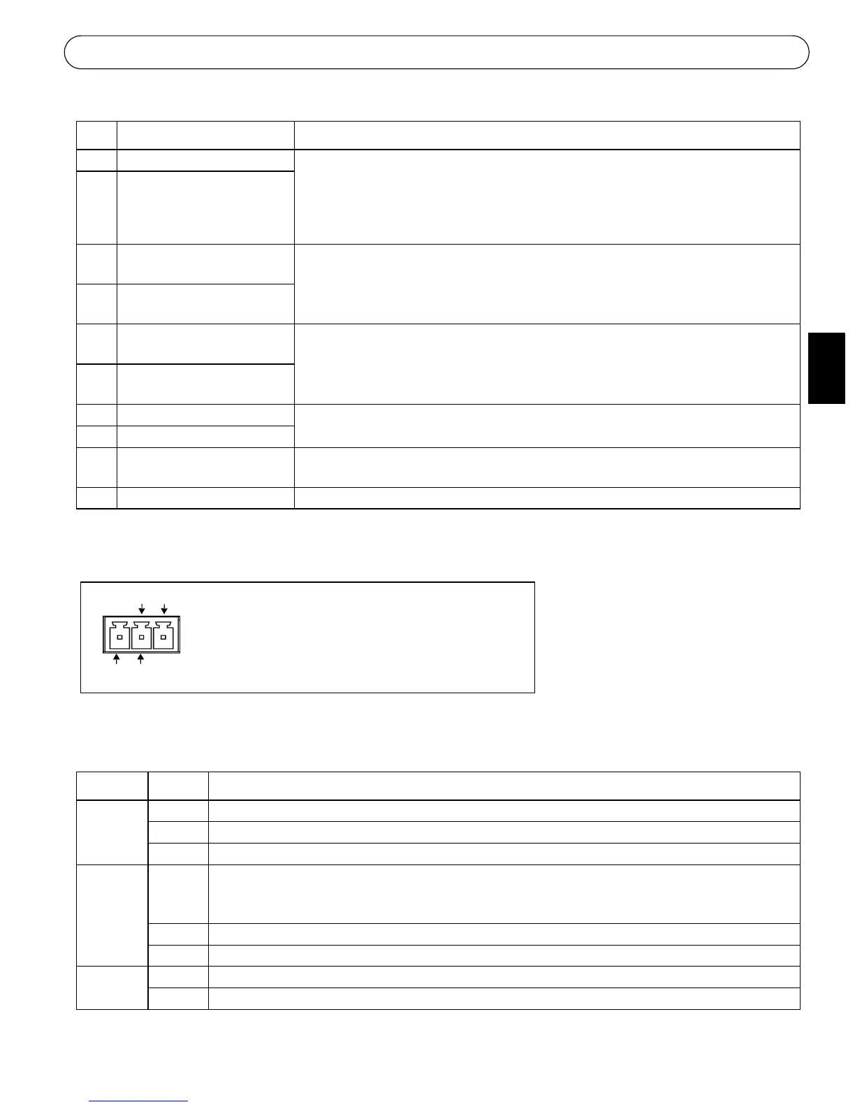
3 pin power connector block
LED indicators
Pin Function Description
1 Output A On the external device output terminals (A and B), there is no distinction between
positive and negative (+ and -). The terminals use a photocoupler and are electri-
cally isolated from the other internal circuitry.
The maximum load should not exceed 100mA and the maximum voltage should be
not more than 50V DC. Note: Connecting AC to the output will damage the unit.
2 Output B
3Digital Input 1
Photocoupler Anode (+)
Photocoupled Input 1. Electrically isolated from the chassis and connectors, this
input can be supplied from an external DC voltage or the DC Power Input/Output
on pins 9 (DC+) and 10 (GND).
4Digital Input 1
Photocoupler Cathode (-)
5Digital Input 2
Photocoupler Anode (+)
Photocoupled Input 2. As above.
6Digital Input 2
Photocoupler Cathode (-)
7 RS-485-A (non-inverting) A half-duplex RS-485 interface for controlling auxiliary equipment.
8 RS-485-B (inverting)
9 DC+ Power Output This can drive the photocoupler inputs or other equipment. The output voltage level
is 3.0 V. A maximum current of 100mA can be sourced from the DC output.
10 GND Ground
LED Color Description
Network Green Steady for connection to 100 Mbit/s network. Flashes for network activity.
Amber Steady for connection to 10 Mbit/s network. Flashes for network activity.
Unlit No connection.
Status Green Shows steady green for normal operation. Note: The Status LED can be configured to be unlit dur-
ing normal operation, or to flash only when the camera is accessed. See the online help files for
more information. Go to Setup > System Options > LED settings
Amber Steady during startup, reset to factory default or when restoring settings.
Red Slow flash for failed upgrade.
Power Green Normal operation.
Amber Flashes green/amber during firmware upgrade.
GND DC+
Connect DC power (7-24V) on pins 1 and 2.
Connect AC power (10-24V) on pins 2 and 3.
AC AC
12
3
 Loading...