AXISA1001NetworkDoorController
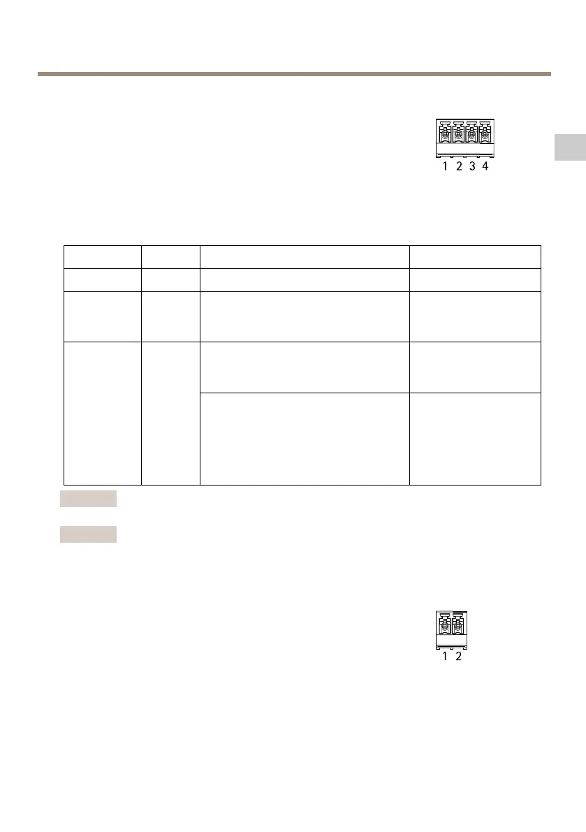
AuxiliaryConnector
4-pincongurableI/Oterminalblockfor:
•Auxiliarypower(DCoutput)
•DigitalInput
•DigitalOutput
•0VDC(-)
Foranexampleconnectiondiagram,seeConnectionDiagramsonpage
28.
FunctionPinNotes
Specications
0VDC(-)
1
0VDC
DCoutput
2
Forpoweringauxiliaryequipment.
Note:Thispincanonlybeusedas
powerout.
3.3VDC
Maxload=100mA
Digitalinput—Connecttopin1to
activate,orleaveoating(unconnected)
todeactivate.
0tomax40VDC
Congurable
(Inputor
Output)
3–4
Digitaloutput—Connecttopin1to
activate,orleaveoating(unconnected)
todeactivate.Ifusedwithaninductive
load,e.g.arelay,adiodemustbe
connectedinparallelwiththeload,for
protectionagainstvoltagetransients.
0tomax40VDC,open
drain,100mA
Important
Therecommendedmaximumcablelengthis30m(98.4ft).
Important
TheoutputcircuitsinthissectionareClass2powerlimited.
PowerConnector
2-pinterminalblockforDCpowerinput.UseaSafetyExtraLowVoltage
(SELV)compliantlimitedpowersource(LPS)witheitheraratedoutput
powerlimitedto≤100Woraratedoutputcurrentlimitedto≤5A.
25
EN