AXISA1001NetworkDoorController
doorcontrollerisremovedfromthewallorceiling.Forinformationabouthowtocongure
alarmsandevents,seetheUserManual.
ConnectionDiagrams
Connectdevicesaccordingtothehardwarepinchartgeneratedthroughthehardware
conguration.Formoreinformationabouthardwarecongurationandthehardwarepinchart,see
ConguretheHardwareonpage41.
AuxiliaryConnector
1
0VDC(-)
2
DCoutput:3.3V,max100mA
A
I/Oconguredasinput
B
I/Oconguredasoutput
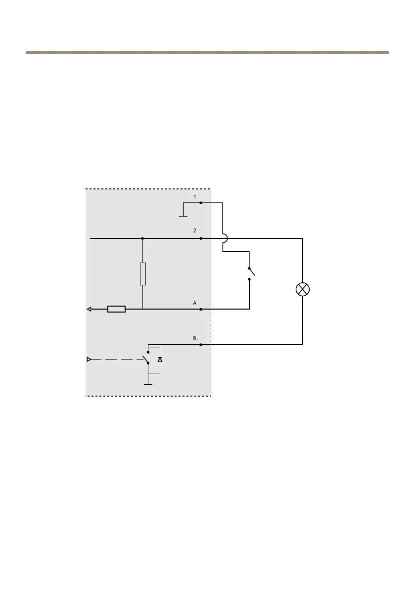
SupervisedInputs
Tousesupervisedinputs,installendoflineresistorsaccordingtothediagrambelow.
28
 Loading...