AXISA1001NetworkDoorController
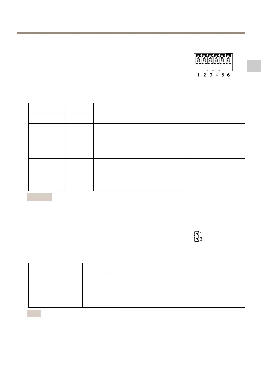
Power&RelayConnector
6-pinterminalblockwithbuilt-inrelayfor:
•Externaldevices
•Auxiliarypower(DCoutput)
•0VDC(-)
Connectlocksandloadstothepinsaccordingtothehardwarepinchart
generatedthroughthehardwareconguration.
FunctionPinNotes
Specications
0VDC(-)
1,4
0VDC
Relay
2–3
Forconnectingrelaydevices.Usethe
hardwarepinchart.SeeCongurethe
Hardwareonpage41.
Thetworelaypinsaregalvanically
separatedfromtherestofthecircuitry.
Maxcurrent=700mA
Maxvoltage=+30VDC
12VDC
5
Forpoweringauxiliaryequipment.
Note:Thispincanonlybeusedas
powerout.
Maxvoltage=+12VDC
Maxload=500mA
24VDC
6
Notused
Important
TheoutputcircuitsinthissectionareClass2powerlimited.
TamperingAlarmPinHeader
Two2-pinheadersforbypassing:
•Backtamperingalarm(TB)
•Fronttamperingalarm(TF)
FunctionPinNotes
Backtamperingalarm
1–2
Fronttampering
alarm
1–2
Tobypassthefrontandbacktamperingalarm
simultaneously,connectjumpersbetweenTB1,TB2and
TF1,TF2respectively.Bypassingthetamperingalarms
meansthatthesystemwillnotidentifyanytampering
attempts.
Note
Boththefrontandbacktamperingalarmsareconnectedbydefault.Thecasingopen
triggercanbeconguredtoperformanactionifthedoorcontrollerisopenedorifthe
27
EN