MACHINE ILLUSTRATION OF THE MILL
PARTS IDENTIFICATION AND DESCRIPTION
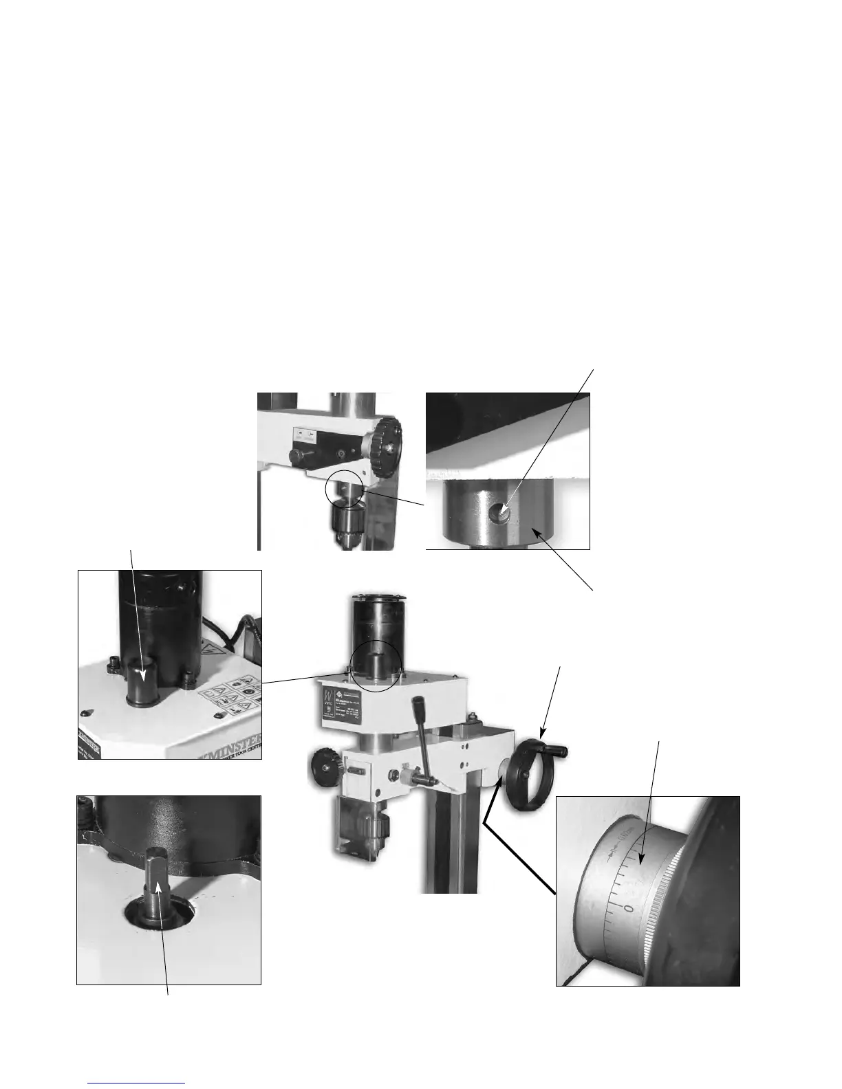
Quill hold pocket The size of the machine precludes any ʻfancyʼ locking mechanism for
the quill. There is a blind pocket on the spindle that accepts the tommy
bar supplied in the tool kit, to enable the spindle to be held in position
whilst the draw bar is loosened.
Draw bar cover A moulded plastic cover that clips into the top of the Motor Gearbox
assembly, to afford protection from the rotating top of the draw bar,
when the quill is at the top of its travel.
Draw bar This is a metal rod, threaded M10 at one end and with an 8mm
(unseen) squared shank and flange machined on the other. It is fitted through the
spindle mandrel to hold the fitted tool/tooling hard into the No2 MT
taper of the spindle shaft.
Draw bar cover
Top of draw bar
Spindle
Blind pocket
30
Fine feed thimble
Rise & fall drive
screw handle