120 • Reference Section
MultiClamp 700A Theory and Operation, Copyright 2000, 2001 Axon Instruments, Inc.
The first step is to fully compensate both the electrode capacitance (using the Cp
Fast/Slow controls) and the whole-cell capacitance (using the Whole Cell controls).
(See Chapter 5,
CAPACITANCE COMPENSATION.) The estimated R
s
– which is the
resistance we wish to compensate – is the M value displayed under the Whole Cell
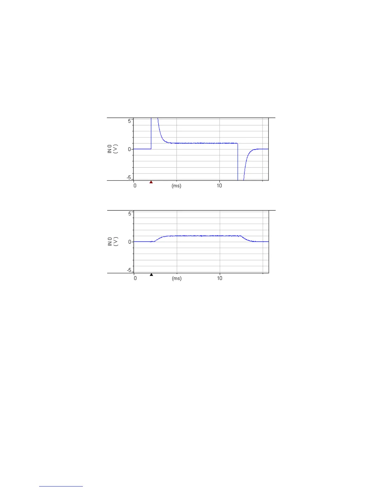
checkbox. After compensation the trace will look like Figure 4.16.
Figures 4.15-4.19. Whole cell responses using PATCH-1U model cell with R
f
= 500 MΩ,
Scaled Output gain = 10 and Seal Test = 100 mV.
Figure 4.15. Uncompensated response (with saturating transients).
Figure 4.16. After compensating transients.
 Loading...