2-2. Check before Installation on the Pipe
Check the following before installing the AGVB control valve on the piping.
1. The specifications printed on the name plate are
appropriate for the use.
2. There is no damage to the valve (including the actuator and
auxiliary equipment).
3. There is no damage to the flanges on the piping.
4. Eyebolts for hoisting are attached to the actuator. If the
eyebolts are used to hoist the control valve, make sure that
the weight including accessories does not exceed the limit
specified in
“Table 2-1. Max. weight for hoisting with
e y e b o l t s”.
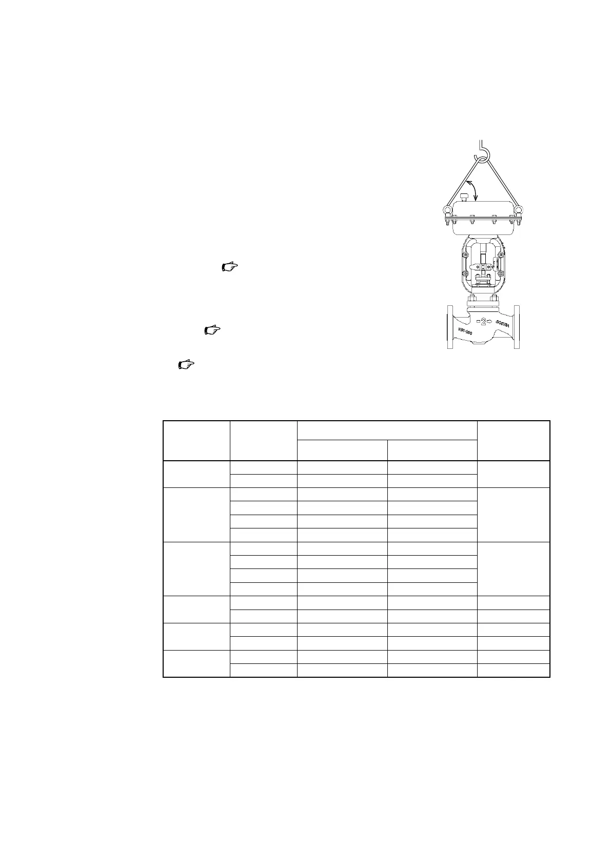
5. If the eyebolts are used to hoist the control valve, the angle
between the actuator and the wire rope must be 60° or
more. (
Figure 2-1).
6. The piping can support the weight of the control valve
(
Table 2-1).
60°
Figure 2-1. Example of hoisting
Table 2-1. Max. weight for hoisting with eyebolts
Unit: kg
Connection
diameter
(inches)
Actuator Product weight (standard bonnet) Max. weight for
hoisting with
eyebolts
Without handwheel With side handwheel
1/2, 3/4, 1 PSA1D, R 17 24 160
PSA2D, R 18 25
1-1/2 PSA1D, R 25 32 160
PSA2D, R 26 33
PSA3D, R 43 44
PSA4D, R 55 56
2 PSA1D, R 26 33 160
PSA2D, R 27 34
PSA3D, R 43 44
PSA4D, R 55 56
2-1/2 PSA3D, R 58 82 160
PSA4D, R 70 100 440
3 PSA3D, R 62 86 160
PSA4D, R 74 104 440
4 PSA3D, R 67 91 160
PSA4D, R 79 109 440
2-4