Chapter 3. Operation
3-1. Trial-Run Inspection and Adjustment
(1) Operation test
Send a 4–20 mA DC or other dummy signal (0 to 100 %) to the valve positioner or
actuator to check that the rated travel is achieved.
Refer to
Table 3-1 and if the allowable value is exceeded, adjust the valve positioner.
For adjustment of the valve positioner, refer to the related user’s manual indicated in
“Chapter 1. Structure of the Control System”.
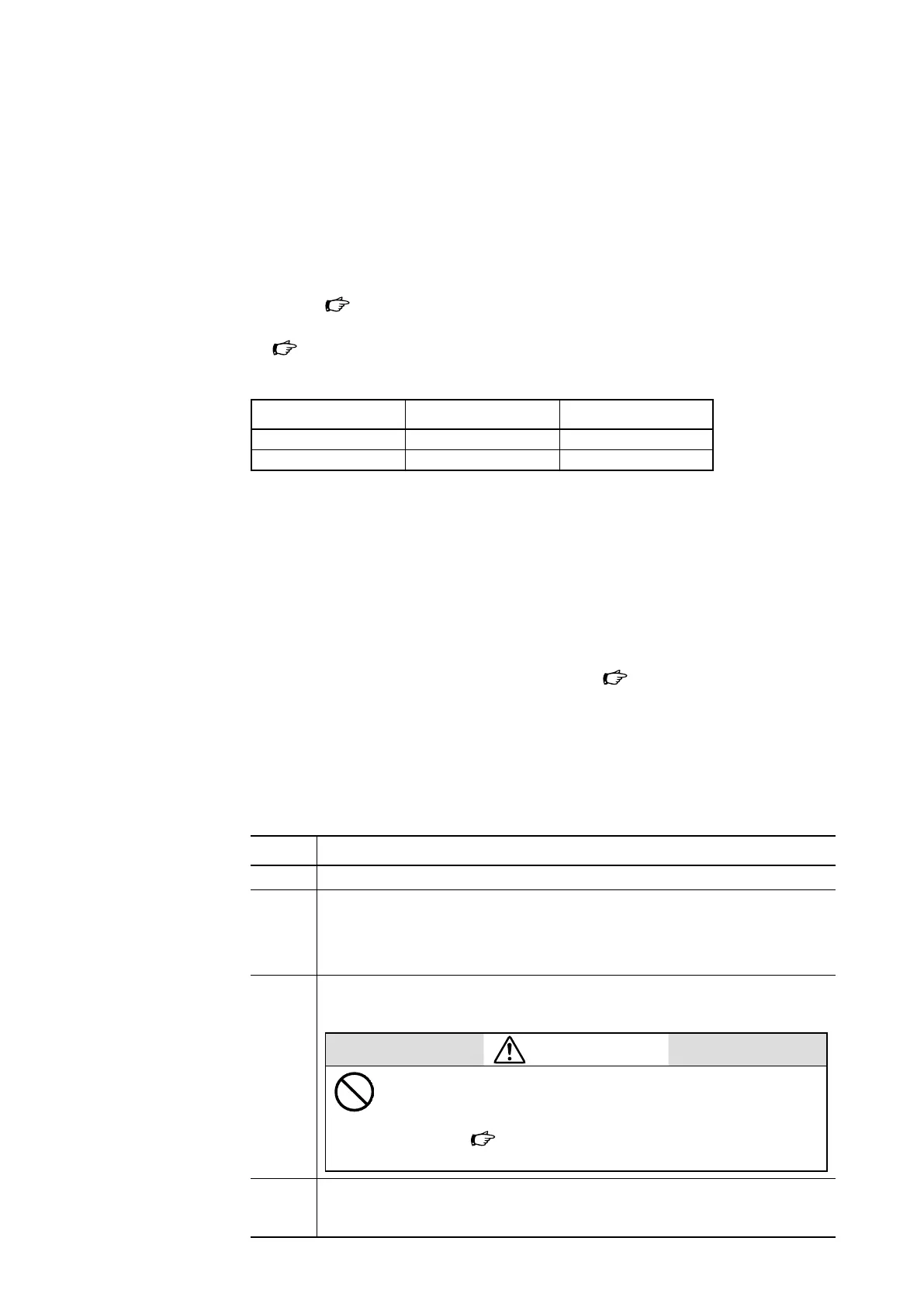
Table 3-1. Control valve performance (when shipped from factory)
Positioner Hysteresis Linearity
AVP, HTP Within 1 % FS Within ±1 % FS
VPE Within 1 % FS Within ±3 % FS
(2) Loop check
Send signals from the host control system, and check that signal wires are connected as
specified and that the functional requirements for control are satisfied.
3-2. Use of the Side Handwheel
This section describes opening and closing the control valve with the side handwheel. If
you need to use the side handwheel, refer to this section. Figure 6-15 illustrates the side
handwheel structure.
Precautions
If the handwheel is used when the equipment is running, make sure that manual opening/
closing of the control valve does not affect the operation of the equipment.
Procedure
Step Procedure
1 Remove the handle lock from the handwheel.
2 Check the OPEN and SHUT arrows cast on the handwheel, and rotate the handwheel in
the desired direction to open or close the valve. The maximum turning torque:
PSA1, PSA2: 190 N
PSA3, PSA4: 450 N
3 When the handwheel does not turn any further, stop trying to turn it and check the
amount of valve travel.
CAUTION
Do not apply excessive force when the mechanical stop posi-
tion of the control valve has been reached. Otherwise you may
damage the valve stem. If the valve stops at an abnormal posi-
tion, refer to “3-3. Troubleshooting” and take the necessary
countermeasures.
4 To resume automatic operation, turn the handwheel until the pointer on the side
handwheel main unit reaches the AUTO position. Lock the handwheel, and resume
automatic operation.
3-1