7-3-3. Reassembly of the Actuator
Precautions
• Check that there is no problem with the parts, referring to the checklist in “4-1-2.
Periodic Inspection” If a problem is found, repair or replace the part as needed.
• The O-ring on the sliding parts should always be replaced at the time of periodic
disassembly. Replace the O-ring on the fixed part if it is deformed, expanded, or damaged
during disassembly.
• Clean the O-ring, oil seal, wear ring, and tape liner O-ring groove, and then apply lubricant
sufficiently.
• Check that any foreign matter produced by maintenance work does not remain on the
cylinder’s sliding parts or in the guide bushing.
z
Actuator with Handwheel
Assembly procedure
In addition to the following instructions, refer to
Figure 7-5.
(1) Assembly of the handwheel section and cylinder
Step Procedure
1 With the yoke (No. 29) set up vertically, place the gear case (No. 30) on it and temporar-
ily attach them together with four hex bolts (No. 12).
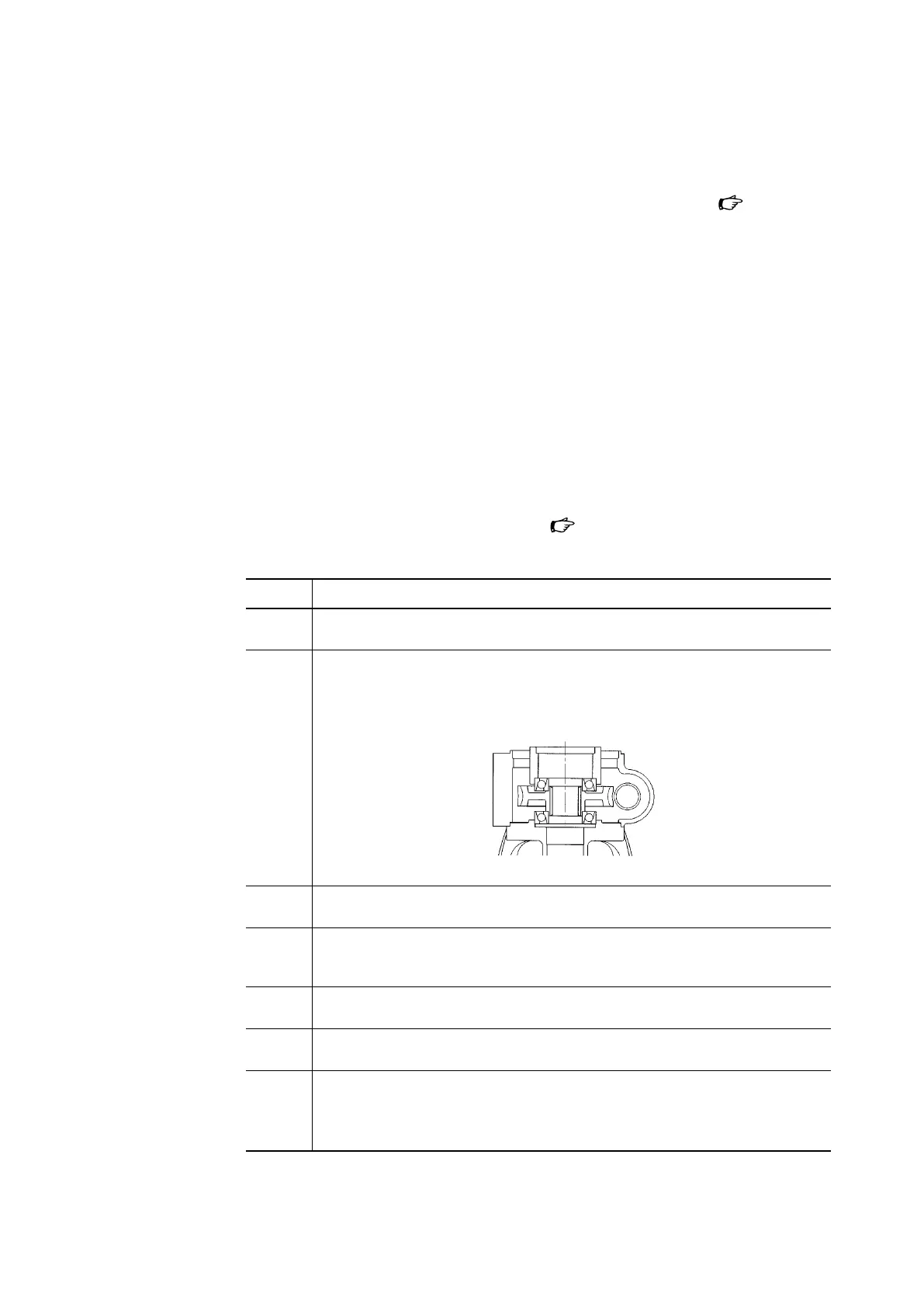
2 Apply lubricanton the upper and lower single-column angular bearings (No. 32), and
assemble the lower bearing, worm wheel (No.33), upper bearing, and the bearing
holder (No. 31) in that order.
Refer to the figure below for how to assemble the bearings and worm wheel.
Figure 7-7.
3 Mount the tape liner (No. 7) on the slide screw (No. 34). From the bottom, screw in the
side screw. Apply lubricant on the threaded part of the slide screw (No. 34).
4 Attach the slide screw rotation lock (No. 49) to the slide screw (No. 34) with the hex bolt
(No. 50) and the hex nut (No. 51). Assemble them so that the recessed part of the screw
rotation lock fits the rib of the yoke.
5 Apply lubricant on the rod packing (No. 22) and the dust seal (No. 24), and assemble
them on the cylinder (No. 21).
6 Place the cylinder (No. 21) on the gear case (No. 30), and temporarily attach them with
four hex bolts (No. 12) and sealing washers (No. 10) that are coated with a liquid sealant.
7 Adjust the position of the the cylinder (No. 21) using the rod (No. 58), check that the rod
moves smoothly, and then tighten screws to the torque specified in Table 7-2.
If the rod does not move smoothly, tap the cylinder or the gear case with a plastic
hammer to adjust the position.
7-10