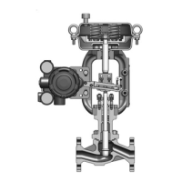
6-3. Mounting the Actuator on the Valve Body
Precautions
For a side handwheel–equipped actuator, attach the side handwheel to the actuator first, and
then mount the actuator on the valve.
Assembly procedure
In addition to the following instructions, refer to
Figure 6-15.
(1) Inspection after reassembly
Step Procedure
1 Apply an anti-galling agent* to the connections of the bonnet, yoke, and the yoke nut.
2 Place the actuator and yoke nut on the valve body. Rotate the actuator so that the
matching marks that were placed before disassembly are aligned.
3 Tighten the yoke nut by hand. Tighten the yoke nut firmly with a hammer and chisel.
* Use Never-Seez made by Bostik, Inc., or the equivalent.
(2) Attaching the stem connector
• For direct-action actuators
Step Procedure
1 Push the valve plug down to set it on the seat.
2 Check the spring range indicated on the nameplate and apply the upper-limit air pres-
sure to the actuator.
3 Further increase the pressure to the supply air pressure.
4 Reduce the air pressure slightly and set the air pressure to the spring range upper limit
again. In this state, temporarily connect the actuator stem and the valve stem with the
stem connector.
5 Decrease the air pressure until the valve travel is several percent. In this state, tighten the
hex bolts of the stem connector to the torque indicated in
Table 6-1.
• For reverse-action actuators
Step Procedure
1 Push the valve plug down to set it on the seat.
2 Check the spring range indicated on the nameplate and apply the lower-limit air pres-
sure to the actuator.
3 Further decrease the air pressure and check that the actuator stem moves several mm in
response.
4 Increase the air pressure slightly, and then lower the air pressure to the spring range
lower limit. In this state, temporarily connect the actuator stem and the valve stem with
the stem connector.
5 Increase the air pressure until the valve travel is several percent. In this state, tighten the
hex bolts of the stem connector to the torque indicated in
Table 6-1.
6-12

 Loading...