Chapter 1. Structure of the Control System
1-1. Introduction
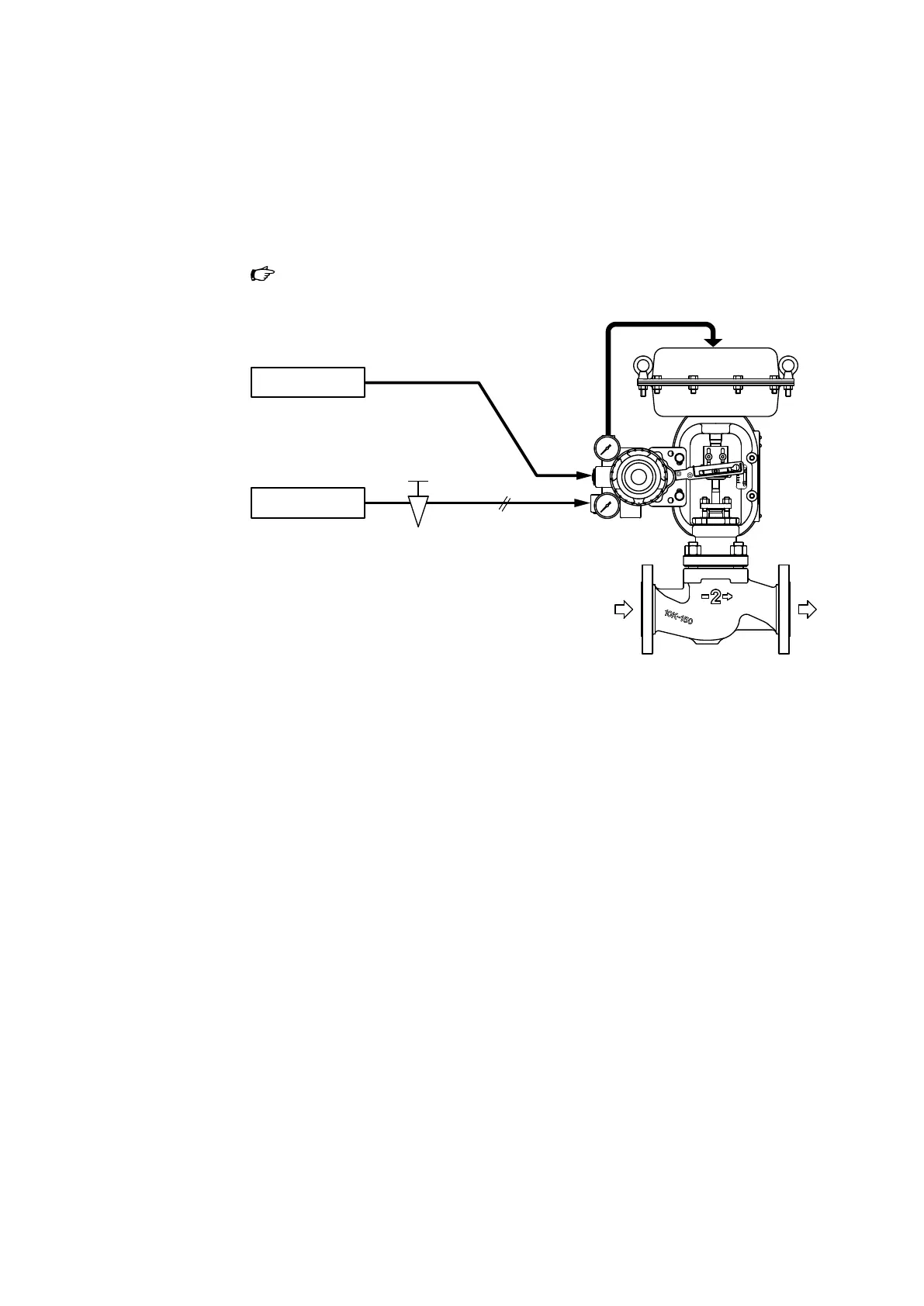
This control valve operates by receiving 4-20 mA DC or 20-100 kPa signals and is driven by
140-490 kPa clean supply air.
Figure 1-1 illustrates a typical control valve system.
Host control system
Air supply system
Air supply
Pressure regulator
with air lter
4–20 mA DC signal
AVP300
Figure 1-1. Control System
This manual contains operating instructions for a model AGVB/AGVM top-guided single-
seated control valve. For details on positioners, refer to the user’s manuals below.
• Pneumatic single-acting valve positioner (model HTP):
document No. OM2-8310-0200
• Pneumatic single-acting valve positioner (model VPE):
document No. OM2-8310-0410
• Smart valve positioner (model AVP300/301/302 (integral type)):
document No. CM2-AVP300-2001
• Smart valve positioner (model AVP200/201/202 (remote type)):
document No. CM2-AVP300-2001
• Smart valve positioner (model AVP701/702):
document No. CM2-AVP702-2001
• Smart valve positioner (with fieldbus)(model AVP703):
document No. CM2-AVP703-2001
1-1