xiv
[3] Adjustment of attachment positions
Procedure for adjustment of attachment positions
Step Procedure
1 Set the A/M switch to manual operation.
(See 5.2, “A/M Switch.”)
2 Supply air, and adjust the actuator air pressure such that the
actuator stem reaches the travel midpoint.
3 Adjust the actuator such that the feedback lever reaches a
90° angle to the valve travel detector's central vertical axis.
Depending on the actuator being used, adjustment may be
performed by moving the valve travel detector, or it may be
performed by moving the pin.
4 Set the A/M switch to automatic operation.
(See 5.2, “A/M Switch.”)
Note: The accuracy specifications can be satisfied by making
the attachment angle 90° ± 2°.
Adjustment of Attachment Positions
3. Air piping and electric wiring connection
[1] Air piping connection
For details, see air piping connection in 2.2, “Installation
Method,” in this document.
[2] Electrical wiring connection (cables between valve
travel detector and positioner)
When shipped from the factory, the valve travel detector and
the positioner body are normally shipped separated at the
connector unit on the positioner body.
Referring to 2.3, “Remote Type Handling,” in this document,
connect the valve travel detector cable to the body of the
device using the remote cable. When laying cable, follow ap-
propriate electrical work guidelines.
4. Auto-setup
(1) Set the input signal to 18 ±1 mA.
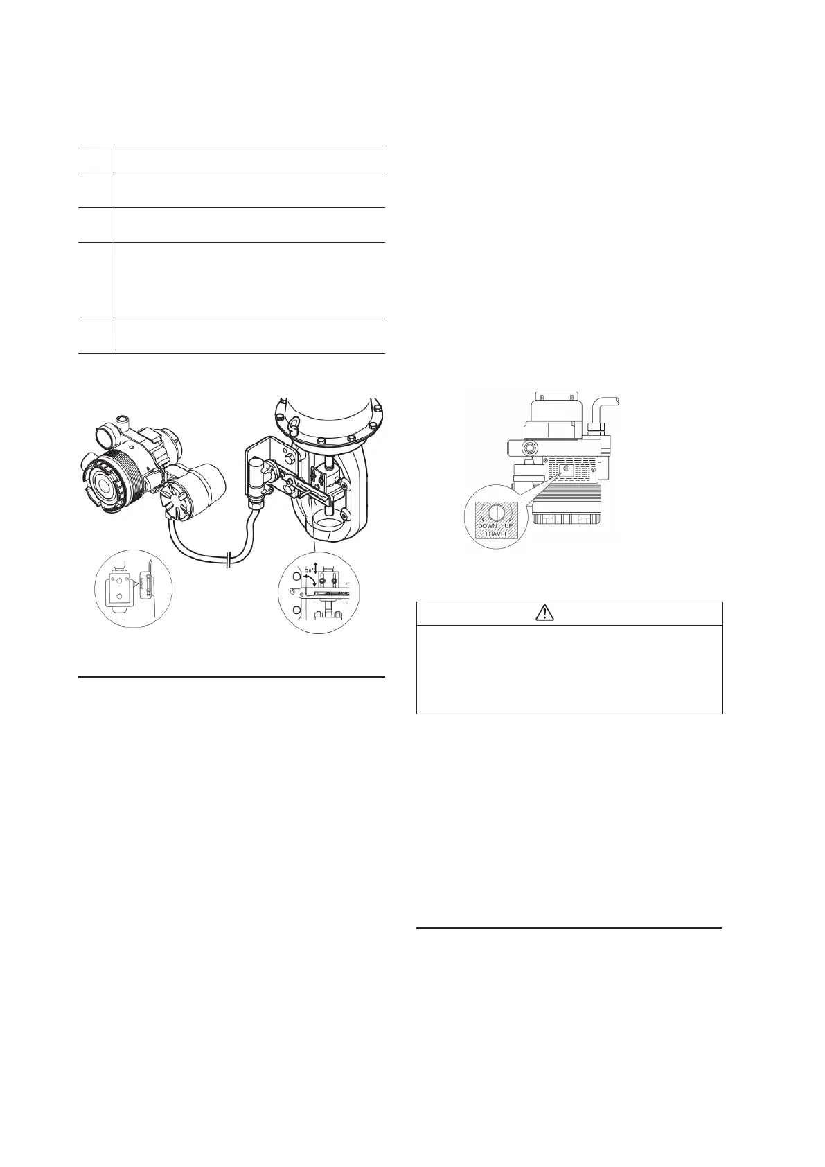
(2) Using a flat-blade screwdriver, turn the external zero/
span adjustment switch in the upper part of the case 90°
in the UP (clockwise) direction (the DOWN direction for
Azbil Corporation's VR and RSA actuators for VFR type
control valves), and hold that position for three seconds.
Note: For reverse close (when the valve's fully closed posi-
tion is on top), set the valve action to reverse close before-
hand. See 4.4.3, “Valve system”
(3) The valve will automatically start to move, and will stop
in about 3 to 4 minutes.
(4) When it stops, adjust it to a position that fits the input
signal.
(5) After that, check whether it has been adjusted correctly.
• Auto-setup can be performed with CommStaff as well.
Warning
When auto-setup is performed, the valve moves from fully
closed to fully open, so there is a danger of, for example,
getting your hand caught or affecting the process.
Before performing auto-setup, move away from the valve,
and confirm that the process is safe.
Check the span point and perform span adjustment.
(1) Set the input signal to the span point (URV). (Zero ad-
justment can be performed if the input signal is adjusted
to the zero point, and span adjustment can be performed
if the input signal is adjusted to the span point.)
(2) Using a flat-blade screwdriver, turn the external zero
span adjustment switch on the upper part of the case in
the UP direction (clockwise) to cause the valve to move
such that the feedback lever rises upward, or turn it
DOWN (counterclockwise) to cause the valve to move
such that the feedback lever drops downward.
5. Operation confirmation
Vary the input signal, and check the zero point and span
point.
Note: When closing the
valve of the single-acting
type device with the lever
in the upward direction,
first set it to reverse close.
If performing auto-setup
DOWN direction:
VFR type
External zero/span adjustment switch
UP direction:
direct type
 Loading...
