2-15
Chapter 2: Installation
2.2.5 Power supply for input signal and travel transmission
■ Input signal
The input signal to the device is 4 to 20 mA. In addition, this input signal is used as the
power supply.
Note
• Do not allow a current of 24 mA DC or higher.
• The device will not operate properly with a current of less than 3.85 mA.
• If the current drops below 3.85 mA, the travel transmission output will go to burn-
out (fail-safe) level (up or down (undefined)).
• When starting from 0 mA, it may take some time until travel changes. After power
is turned on, use a 3.85 mA or greater signal. In this state, response time will not be
slow. On the contrary, when using a 3.85 mA or greater signal, if the flow pressure
fluctuates greatly when the valve is fully closed, overshoot may occur at the first
startup. To suppress overshoot, temporarily lower the input signal to 0 mA.
Caution
•
Do not apply excessive voltage (for example, connecting a 24 V DC power supply
without resistance) to the input signal terminal. Doing so can cause the electric
board to burn out, and the device to fail.
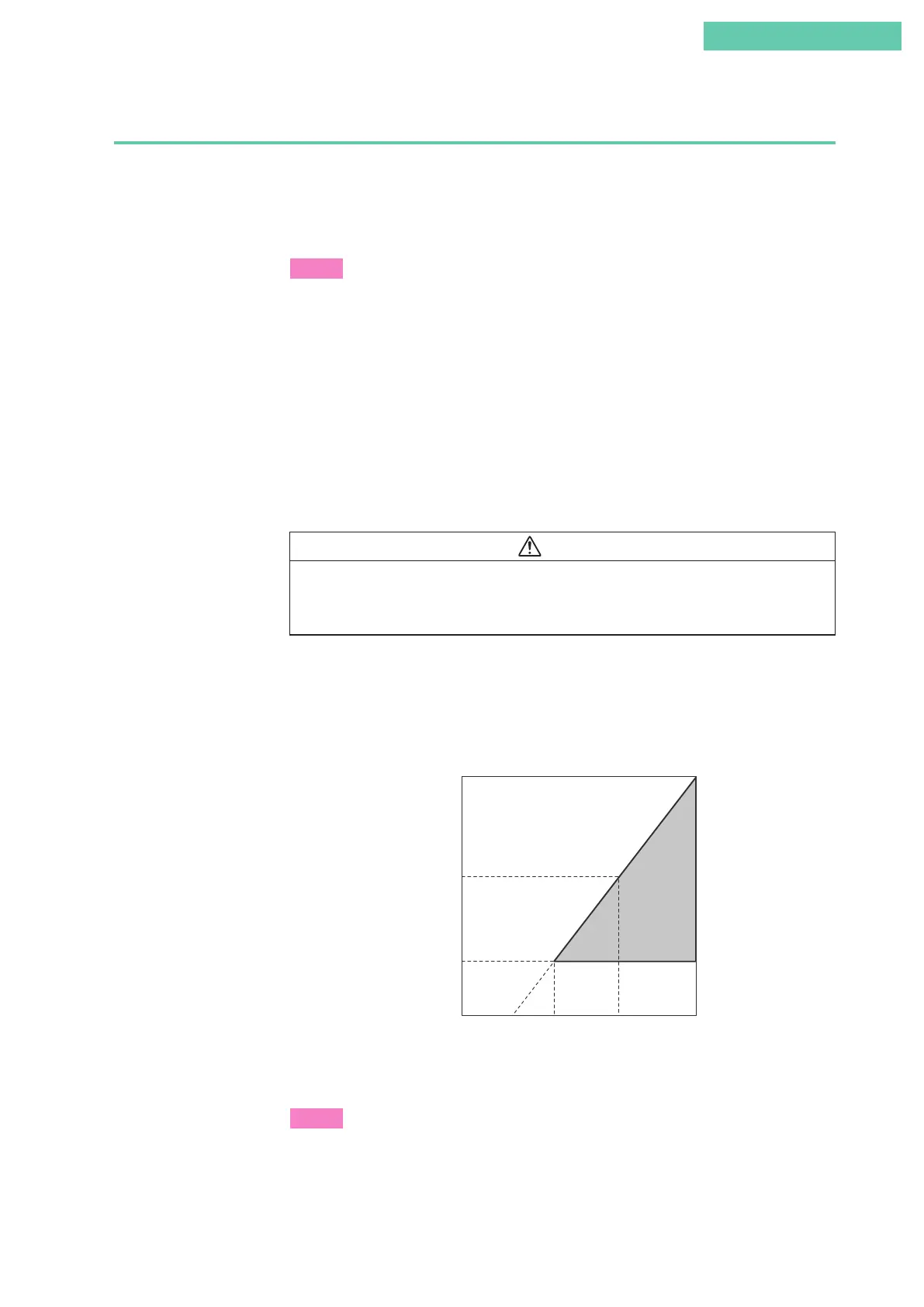
■ Power supply and load resistance for travel transmission
Make sure that the load resistance of the electric lines connected to the travel transmis-
sion loop, with respect to the power supply voltage used, is within the operable range
shown in the diagram below.
605
1560
245
16.5 24 450
Load resistance (Ω)
Supply voltage (V DC)
Operable range
Figure 2-16. Supply Voltage and Load Resistance Characteristics
Note
Do not apply a voltage of 45 V or higher.
 Loading...
