3-3
Chapter 3: Operation
3.1.1 Overview of auto-setup
Use this procedure to automatically set the following items.
(1) Zero/span adjustment
(However, by default the span point is set so that the overstroke becomes 10%. If
a span adjustment is done after auto-setup, the device changes and saves the over-
stroke setting.)
(2) Configuration of actuator operation
(3) Configuration of the LRV (lower range value, the input signal at 0%) and URV
(upper range value, the input signal at 100%) of the input signal
• If actuator operation is reverse operation: LRV = 4 mA, URV = 20 mA
• If actuator operation is direct operation: LRV = 20 mA, URV = 4 mA
(4) Configuration of actuator size (Param)
(5) Configuration of hysteresis difference (Hys)
(Set the gland packing hysteresis difference from among three types: LIGHT, ME-
DIUM, and HEAVY.)
(6) Travel transmission fail-safe setting
Warning
•
During auto-setup the valve moves from fully closed to fully open. Take appropriate
measures beforehand to ensure that the movement of the valve will not cause injury
or have an effect on the process.
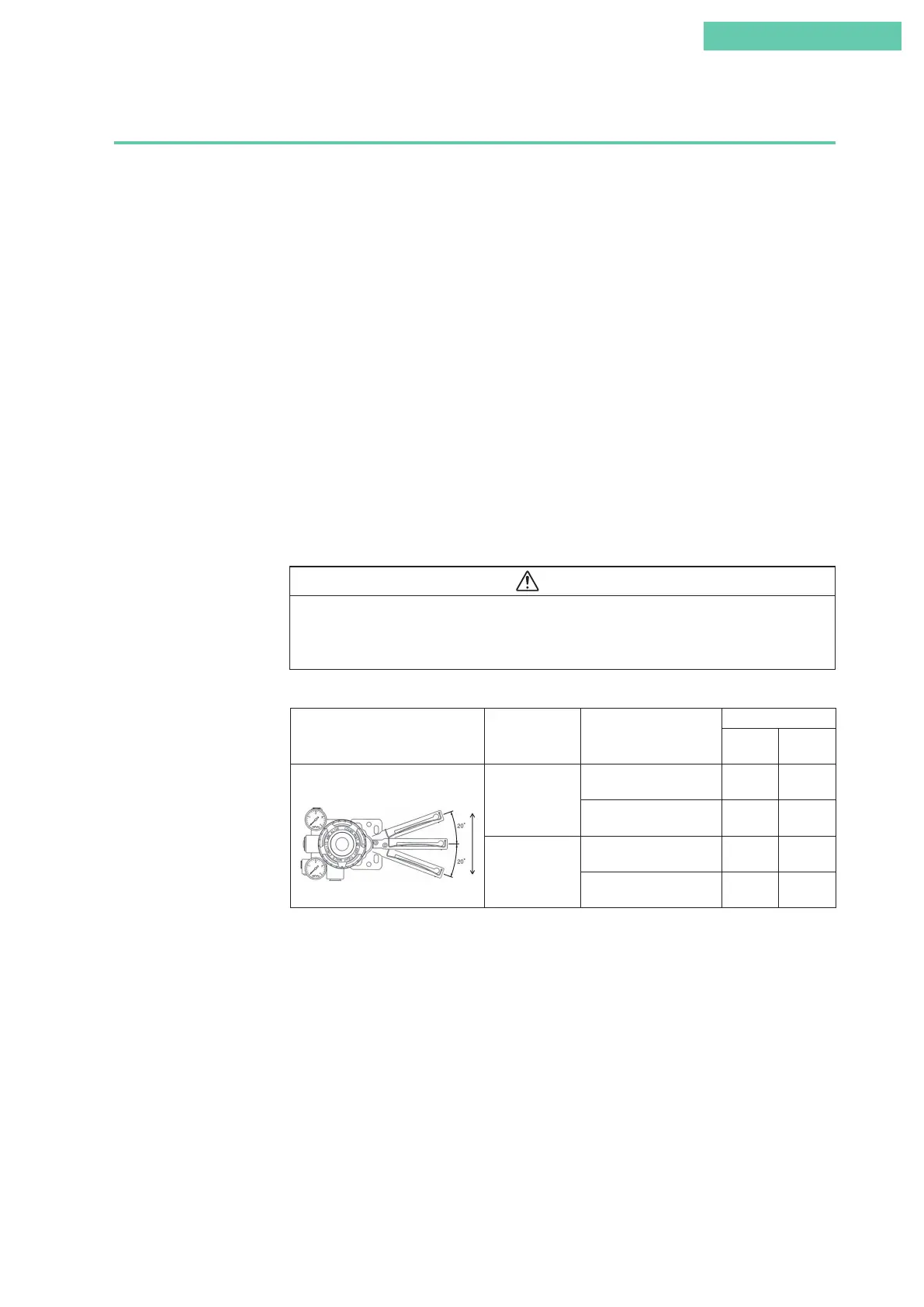
Table 3-1. Integral type setting
Lever Movement Valve Direction Valve Control Action
Setting
Actuator
Action
Valve
Action
Up → Down
Closed → Open
Direct (Closed: 20 mA;
open: 4 mA)
Reverse Reverse
Reverse (Closed: 4 mA;
open: 20 mA)
Direct Reverse
Open → Closed
Direct (Closed: 20 mA;
open: 4 mA)
Direct Direct
Reverse (Closed: 4 mA;
open: 20 mA)
Reverse Direct
If the valve action parameters to which the device is configured using Tables 3-1 and 3-2
are the reverse close (REVERSE) values, see 4.4.3, “Valve system,” in this document, and
set valve action to the reverse close settings.
If the valve action parameters to which the device is configured using Tables 3-1 and
3-2 are the direct close (DIRECT) values, no parameter configuration is required. (The
device is shipped from the factory set to “direct close (DIRECT).”)
Up
Down
 Loading...
