Appendix A: Specifications
A-5
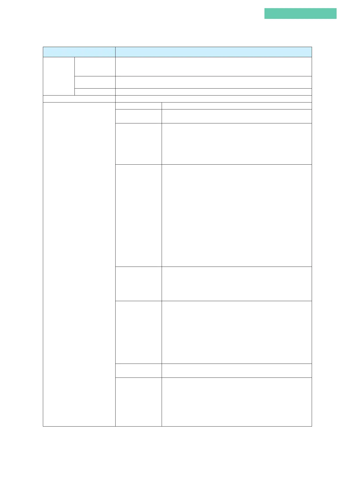
Item Specification
Performance Accuracy For 8 mA≤input signal span < 16 mA: ±1%F.S. (±2.5% with user-defined flow characteristics)
For 4 mA≤input signal span < 8 mA: ±1.5%F.S. (Refer to Table 1. Because accuracy varies depending
on the combination of actuator size and travel.)
Travel transmission
accuracy*
±1%F.S. (±2.5% with user-defined flow characteristics)
Stroke coverage 14.3 to 100 mm Stroke (Feedback Lever Angle ±4° to ±20°)
Enclosure classification JIS C0920 watertight, NEMA type 4X, IP66
Approvals TIIS Flameproof Ex d IIC T6 X
KOSHA Flameproof Ex d IIC T6
Flameproof cable gland must be Ex d IIC approved.
FM Explosionproof Explosionproof: Class I, Division 1, Group A, B, C, D
Dust-ignition: Class II, Division 1, Group E, F, G
Suitable: Class III, Division 1
Flameproof: Class I, Zone 1, AEx d IIC T6 at T
amb
<80°C
NEMA Type 4X
Installation should comply with NEC.
FM Intrinsically safe Intrinsically safe: Class I, II, III, Division 1, Group A, B, C, D, E, F, G, T4
Intrinsically safe: Class I, Zone 0, AEx ia IIC T4
Nonincendive: Class I, Division 2, Group A, B, C, D, T5
Suitable: Class II, III, Division 2, Groups F, G, T4
NEMA Type 4X, IP66
The barriers should be FM recognized types and comply with the following
conditions as follows:
Input circuit(terminals ±IIN)
Model AVP300/301: 12.02≤V
max
≤30 V, I
max
=100mA, Pi=1 W,
Ci=18.26 nF, Li=0.22 mH
Model AVP302: 12.02≤V
max
≤30 V, I
max
=100 mA, Pi=1 W, Ci=41 nF,
Li=0.22 mH
Output circuit(terminals ±OUT)
Model AVP301: V
max
=30 V, I
max
=100 mA, Pi=1 W, Ci=22 nF,
Li=0.22 mH
Installation should comply with NEC.
ATEX Flameproof II 2 G Ex db II C T6 Gb −40°C≤T
amb
≤+75°C
IEC IP66
Flameproof cable gland must be Ex db IIC approved.
Note: IP66 waterproof and dust-proof performance can be assured by installing
an appropriate cable gland.
ATEX Intrinsically
safe
II 1 G Ex ia IIC T4
II 1 D Ex iaD 20 IP66 T135°C
IEC IP66
The barriers should be ATEX certified types and comply with the following
condition as follows:
Input circuit (terminals ±IIN)
Model AVP300/301: Ui=30 V, Ii=100 mA, Pi=1 W, Ci=1 nF, Li=0.2 mH
Model AVP302: Ui=30 V, Ii=100 mA, Pi=1 W, Ci=26 nF, Li=0.2 mH
Output circuit (terminals ±IOUT)
Model AVP301: Ui=30 V, Ii=100 mA, Pi=1 W, Ci=3 nF, Li=0.2mH
NEPSI Flameproof Ex d IIC T6 Gb, Ex tD A20 IP66 T85 °C
Flameproof cable gland must be NEPSI Ex d IIC approved.
NEPSI Intrinsically
safe
Ex ia IIC T4-T6 Ga
The barriers should be NEPSI certified types and comply with the following
condition as follows:
Input circuit (terminals ±IIN)
Model AVP300/301: Ui=30 V, Ii=100 mA, Pi=1 W, Ci=5 nF, Li=0.22 mH
Model AVP302: Ui=30 V, Ii=100 mA, Pi=1 W, Ci=41 nF, Li=0.22 mH
Output circuit (terminals ±IOUT)
Model AVP301: Ui=30 V, Ii=100 mA, Pi=1 W, Ci=22 nF, Li=0.22 mH
 Loading...
