Introduction
xxi
Combination of model AVP200/201/202 (remote type) and double-acting rotary cylinder
actuator
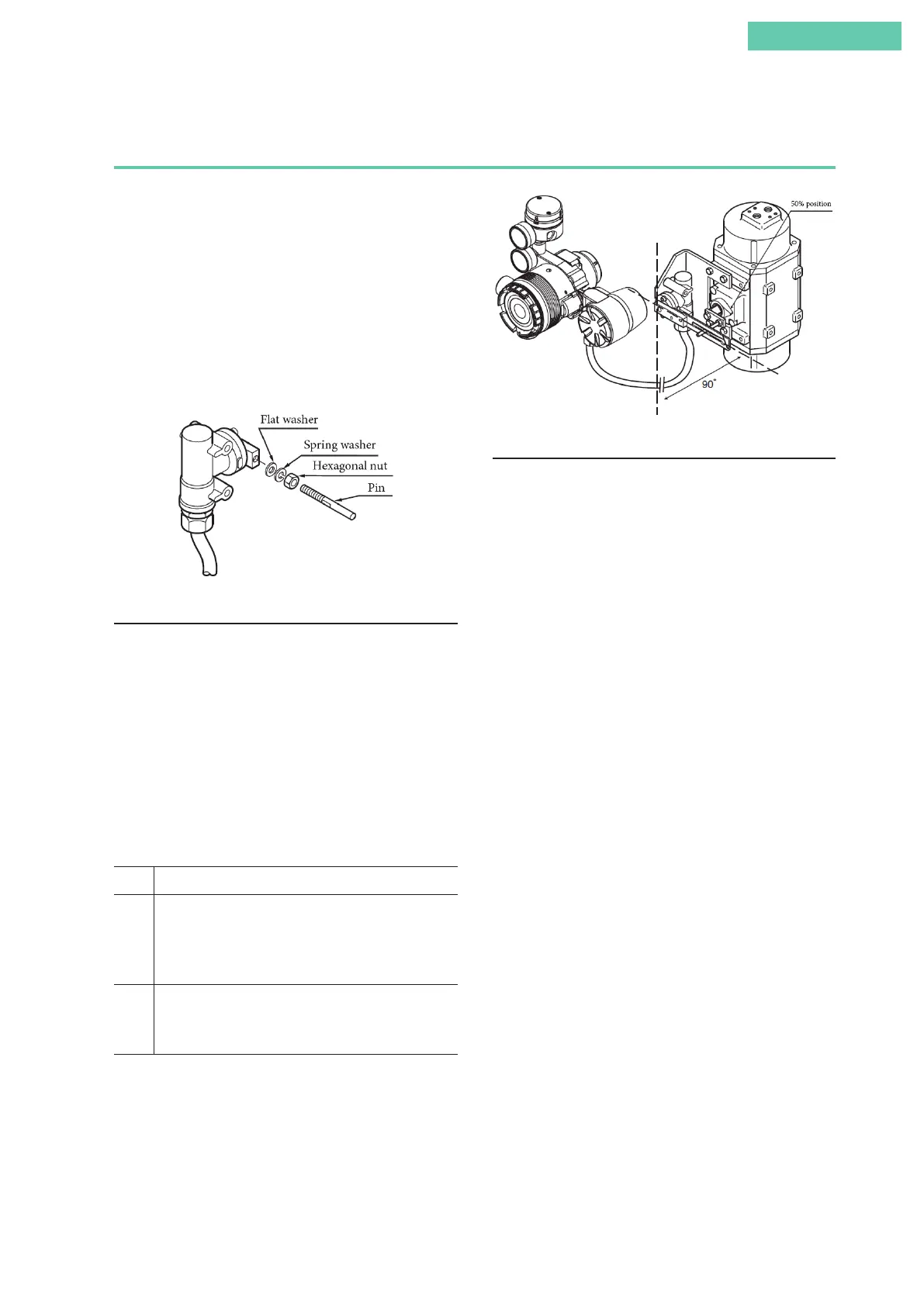
1. Attachment of feedback lever (pin)
In order to minimize the risk of damage to the feedback lever
while it is carried or transported, and to minimize the pack-
aging as well, the feedback lever is detached from the valve
travel detector when it is packed. As a result, the feedback
lever (pin) must be attached to the valve travel detector prior
to installation of the device.
Using the two accompanying hexagonal nuts, attach the feed-
back lever (pin) firmly to the valve travel detector as shown
in the diagram.
Attachment of Feedback Lever (Pin)
2. Attachment and installation
[1] Attachment to the actuator of the valve travel detector
When attaching the valve travel detector to the actuator,
install the cable outlet such that it does not face upward. If it
faces upward, change the direction of the feedback lever. For
details, see 2.3, “Remote Type Handling.”
[2] Positioner body configuration
Install the body of the positioner onto the 2B stanchion.
[3] Adjustment of attachment positions
Procedure for adjustment of attachment positions
Step Procedure
1 Using for example the manual handle of the actuator or
manual operation via the external pressure regulator with
filter, set the position to 50 %.
(With a double-acting actuator, manual operation cannot be
performed using the A/M switch.)
2 By adjusting the attachment position of the arm that
holds up the feedback pin, adjust the actuator such that
the feedback lever reaches a 90° angle to the valve travel
detector's central vertical axis.
Note: The accuracy specifications can be satisfied by making
the attachment angle 90° ±2°.
Adjustment of Attachment Positions
3. Air piping and electric wiring connection
[1] Air piping connection
(1) If control operation of control valve is direct operation
This refers to the state in which the valve moves in the
closing direction as the input signal increases. Connect
the reversing relay output OUT1 to the cylinder chamber
that performs output in order to close the valve in re-
sponse to increased pressure.
Next, connect the reversing relay output OUT2 to the
cylinder chamber that performs output in order to open
the valve in response to increased pressure.
(2) If control operation of control valve is reverse operation
This refers to the state in which the valve moves in the
opening direction as the input signal increases. Connect
the reversing relay output OUT2 to the cylinder chamber
that performs output in order to close the valve in re-
sponse to increased pressure.
Next, connect the reversing relay output OUT1 to the
cylinder chamber that performs output in order to open
the valve in response to increased pressure.
For details, see air piping connection and electric wiring
connection in 1.3, “Description of Device Structure and
Functions,” and 2.2, “Installation Method,” in this docu-
ment.
[2] Electrical wiring connection (cables between valve
travel detector and positioner)
When shipped from the factory, the valve travel detector and
the positioner body are normally shipped separated at the
connector unit on the positioner body.
Referring to 2.3, “Remote Type Handling,” in this document,
connect the valve travel detector cable to the body of the de-
vice using a special-purpose connector. When laying cable,
follow appropriate electrical work guidelines.
 Loading...
