2-6
■ Installation procedure
The general installation procedure is shown below.
Step Procedure
1 Fasten the mounting plate securely to the rear of the positioner using the two hexagonal
bolts (M8×20) and spring washers provided.
2 Fasten the positioner (mounting plate) securely to the actuator's mounting structure using
the bolts and washers provided. During this operation, pass the actuator's feedback pin
through the slot in the positioner's feedback lever.
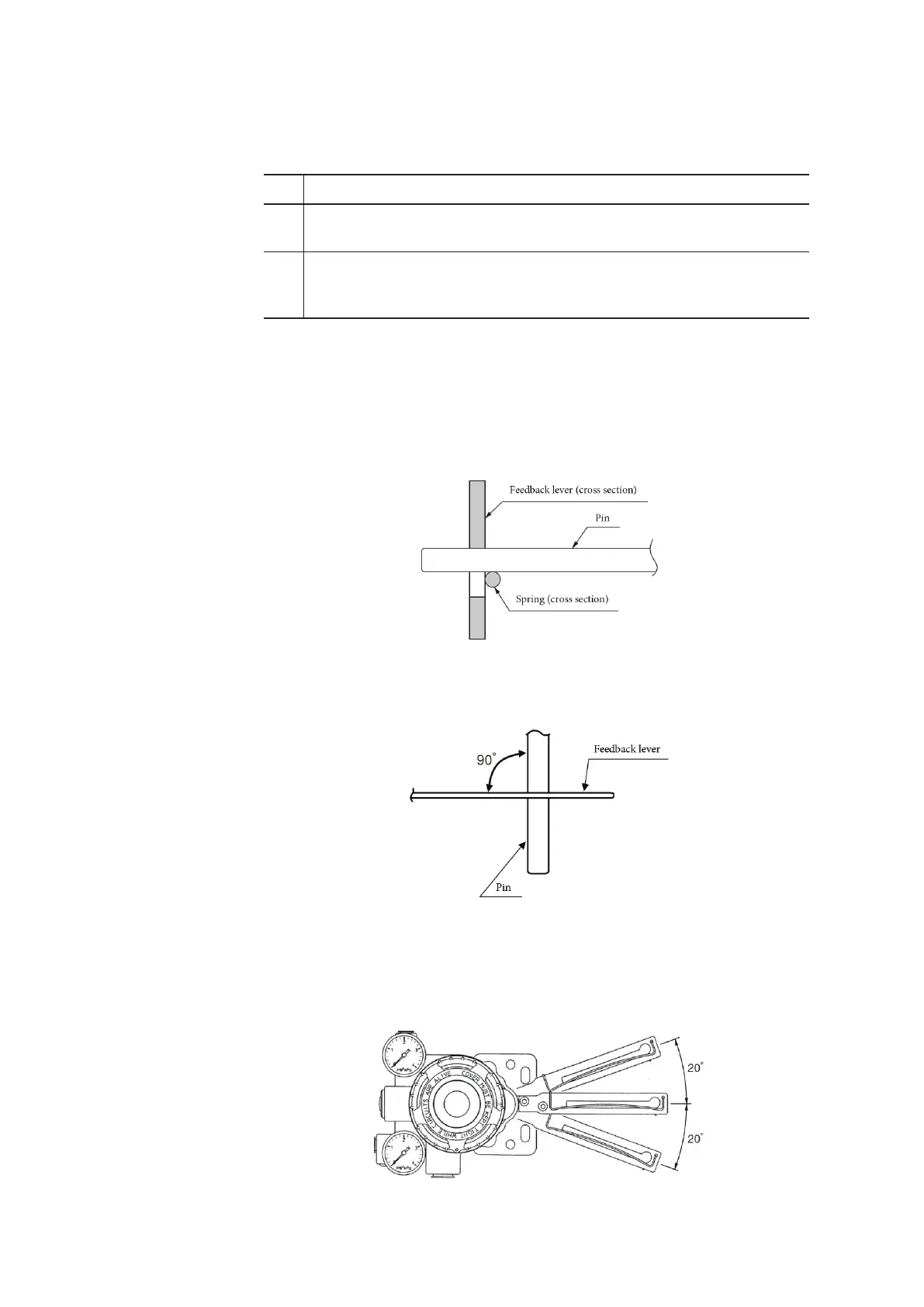
■ Connection of feedback pin and feedback lever (1)
The following points must be observed when connecting the device’s feedback lever and
the actuator’s feedback pin. Be sure to connect these correctly.
(1) Only a 6 mm diameter pin may be used.
(2) The pin should be clamped.
Figure 2-2. Attachment of Feedback Lever and Feedback Pin
(3) The angle between the feedback lever and pin must be 90° when viewed from
above.
Figure 2-3. Angle between Feedback Lever and Pin
(4) The allowable rotation angle of the feedback lever is ±20° from the horizontal. If
±20° is exceeded, a major failure (VTD FAULT) will be detected by the self-diag-
nostics, and the device will not operate properly. (The minimum rotation angle for
guaranteed accuracy is ±4°.)
Figure 2-4. Feedback Lever Operating Angle
 Loading...
