2-19
Chapter 2: Installation
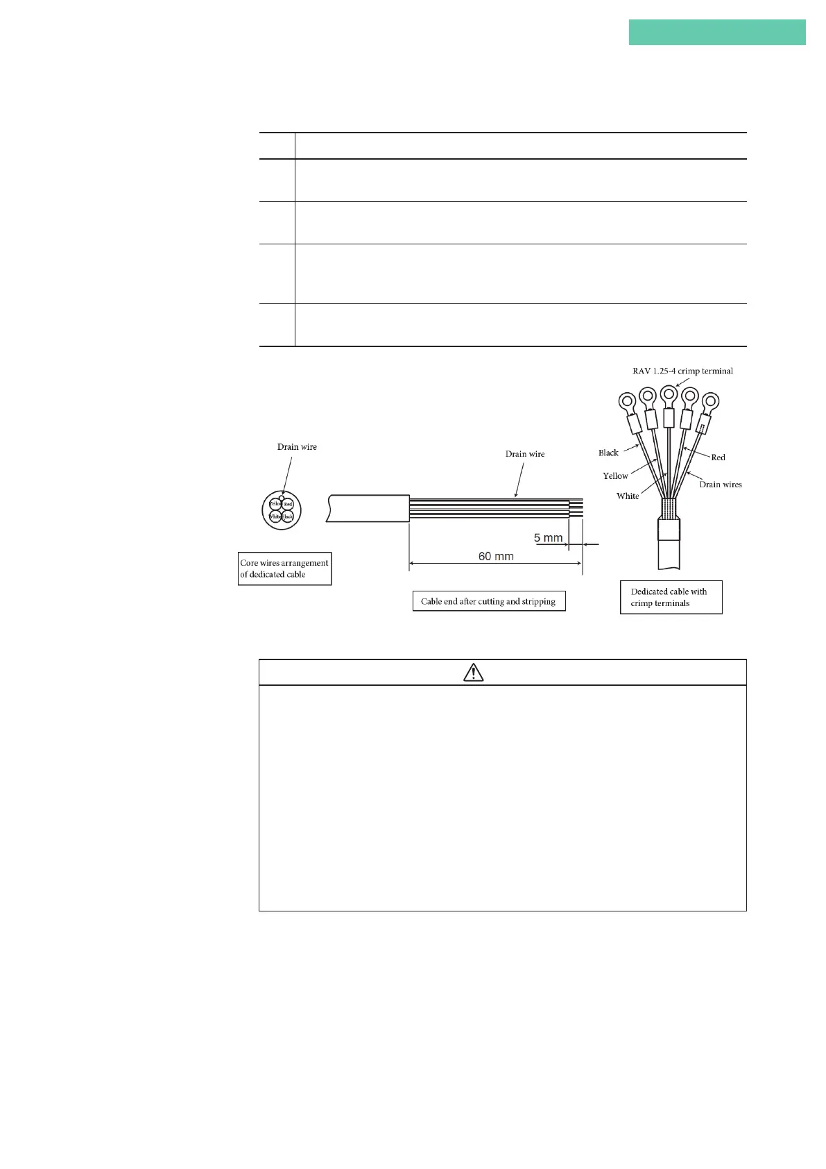
■ Adjusting length of remote cable
Step Procedure
1 Remove the remote cable from the terminal box, and then cut a remote cable of a suitable
length.
2 Strip off about 6 cm of the sheath from the end of the cable, and strip off about 5 mm of
the insulation of the wire.
3 Insert the drain wire into the heat-shrinkable tubing, and shrink the heat-shrinkable
tubing by applying an appropriate amount of heat to it. (If there is no heat-shrinkable
tubing, take measures so that the drain wire can be insulated from the other wires.)
4 Crimp the wires and the RAV1.25-4 crimp terminals (wire diameter 1.25 mm, M4 round
crimp terminals) with an appropriate crimping tool.
Figure 2-19. Adjusting the Length of the Cable
Caution
•
When connecting or disconnecting positioner body cables, do not allow contami-
nants, rainwater, and the like to enter the valve travel detector unit or the positioner
body.
• Periodically tighten the watertight gland and flameproof cable gland. Failure to do
so may allow rainwater to enter the equipment, resulting in malfunctions.
• The cable cannot be removed from the valve travel detector unit. However, the wa-
tertight gland can be removed.
• Do not remove the flameproof cable gland on the valve travel detector. Doing so
could cause wires inside the cable to be broken as a result of the rotation of the
cable.
 Loading...
