2-26
■ Flameproof cable gland installation procedure for use at 200
series main part
The flameproof cable gland installation procedure is shown below.
Step Procedure
1
Securely fasten the body to the terminal box connection or the universal elbow
connection.
Note
• Apply adequate waterproofing to these parts. We recommend the use of silicone resin
based non-hardening sealant materials.
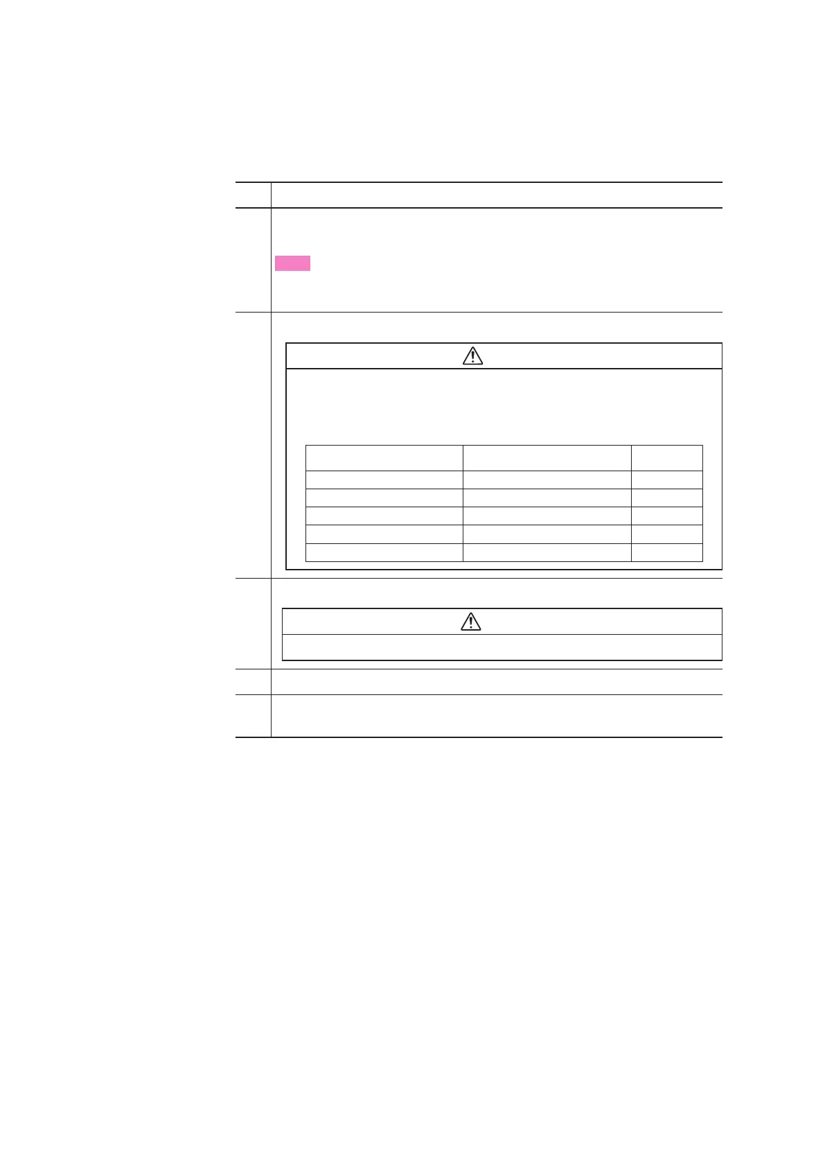
2 Refer to the illustrations and insert the cable carefully.
Warning
• If the respective diameters of the cable and the packing do not match, it may not
be possible to prevent flames from escaping and causing personal injury. Refer-
ring to the table below, select packing that has an internal diameter that is appro-
priate for the outer diameter of the cable.
Cable Outer Diameter (mm) Packing Inner Diameter (mm) Notes
7.0 to 8.0 8 Provided
8.1 to 9.0 9 Provided
9.1 to 10.0 10 Built in
10.1 to 11.0 11 Provided
11.1 to 12.0 12 Provided
3 Fit the gland onto the guide ring and tighten it to fasten it in place.
Warning
• To prevent injuries from escaping flame, be sure to tighten the packing sufficiently.
4 Insert the end of the cable into the terminal box.
5 Screw the cover onto the body and tighten it securely to hold it in place, and then tighten
the hex socket setscrew on the cover.
 Loading...
