2-2
2-1. Item to be checked after installation and before starting operation
(1) Check that there is no leak from air piping.
(2) Check that the bolts and nuts of the diaphragm case are not loose. Standard tight.ening
torques are as follows:
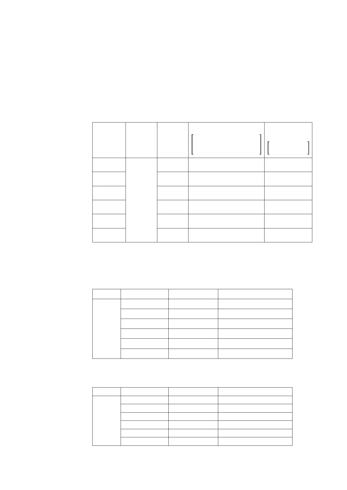
(3) Tighten the packing flange nuts to prevent leak from the gland packing chapter. Standard
tightening torques are as shown in Table 2-2.
Table 2-2. Tightening Torques of Packing Flange Nuts
Unit: N•m{kgf/cm
2
}
Valve Stem
Diameter
(mm)
V PTFE
packing
PTFE Yarn
Packing
(P4519)
Expanded graphite Packing V PTFE + PTFE
P6610CH + P6528
P6610CH + M8590
T2200 + P6710CH (Type2)
Yarn Packing
PTFE + V7233
PTFE + TK2006
10
1 {8}
9 {90} 5 {50} 3 {30}
13 15 {150} 8 {80} 5 {50}
16 24 {240} 13 {130} 8 {80}
20 32 {320} 18 {180} 10 {100}
25 - - 28 {280} 15 {150}
30 66 {660} 36 {360} 20 {200}
Note: The tightening torques mentioned in the above are only to give you reference values.
Note that tightening torques may vary depending on the type of packing.
Table 2-3. Tightening Torques of packing Flange Nuts for PTFE yarn (Certified ISO
15848-1-compliant low-emission gland packing)
Model Actuator model Stem size Tightening torque
HLS,HLC
HTS,HSC
HA2
φ
10 mm 12 N·m
HA3
φ
13 mm 20 N·m
HA3
φ
16 mm 33 N·m
HA4
φ
20 mm 44 N·m
PSA6,DAP560
φ
30 mm 54 N·m
DAP1000(X)
φ
40 mm 65 N·m
Table 2-4. Tightening Torques of packing Flange Nuts for expanded graphite (Certified ISO
15848-1-compliant low-emission gland packing)
Model Actuator model Stem size Tightening torque
HLS,HLC
HTS,HSC
HA2
φ
10 mm 12 → 0 (loosening) → 8 N·m
HA3
φ
13 mm 20 → 0 (loosening) → 13 N·m
HA3
φ
16 mm 33 → 0 (loosening) → 22 N·m
HA4
φ
20 mm 44 → 0 (loosening) → 30 N·m
PSA6,DAP560
φ
30 mm 54 → 0 (loosening) → 36 N·m
DAP1000(X)
φ
40 mm 85 → 0 (loosening) → 43 N·m
 Loading...


