4-25
4-6. Disassembly and assembly of model PSA6 actuator
Structure
This actuator is comprised of a cylinder, spring unit, lift stopper, spring retainer, hex stay,
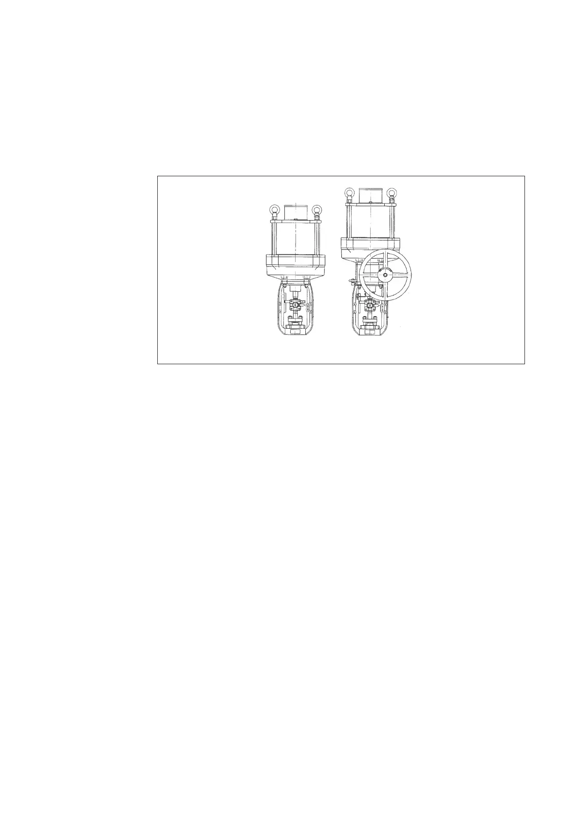
yoke, manual handwheel and a single action positioner. For an external view of the a actuator,
refer to "Figure 4-22 Exterior of Model PSA6R".
Figure 4-22 Exterior of Model PSA6R
Assembly on valve body
The Assembling nuts are integral to the valve body connect the yoke and valve body. The stem
connector connects the actuator's rod and valve stem.
Air piping connection
The tubing is connected to the single action positioner when used as a control valve. Refer to
the following instruction manuals for details on the single action positioners.
• Pneumatic positioner (Model HTP) No. OM2-8310-0200
• Electro-pneumatic positioner (Model HEP) No. OM2-8310-0100
• Electro-pneumatic positioner (Model AVP 300/301/302/200/201/202)
No. CM2-AVP300-2001
• Electro-pneumatic positioner (Model AVP 303/203) No. CM2-AVP303-2001
• Smart valve positioner 700 series with HART type (Model AVP701/702)
No. CM2-AVP702-2001
• Smart valve positioner 700 series with F
OUNDATION
Fieldbus type (Model AVP703)
No. CM2-AVP703-2001
Calibration
This actuator does not require any calibration.
When connecting the valve stem of the valve body with the actuator's rod using a stem
connector, adjustment should be made to sit the valve plug onto the seat ring. Then screws on
actuator's scale plate are loosened, and the stroke and index matched to properly position the
scale plate.
 Loading...


