4-11
4-3. Disassembly and assembly of actuator
Normally the actuator requires no adjustment. However, it should be disassembled and
assembled when installing it on a valve body, when modifying its specifications, or when
replacing damaged parts. The disassembly and assembly procedure of the actuator for such
purposes are covered in Sections 4-4 and 4-5. To disassemble the actuator, refer to Figure 4-7
to Figure 4-21.
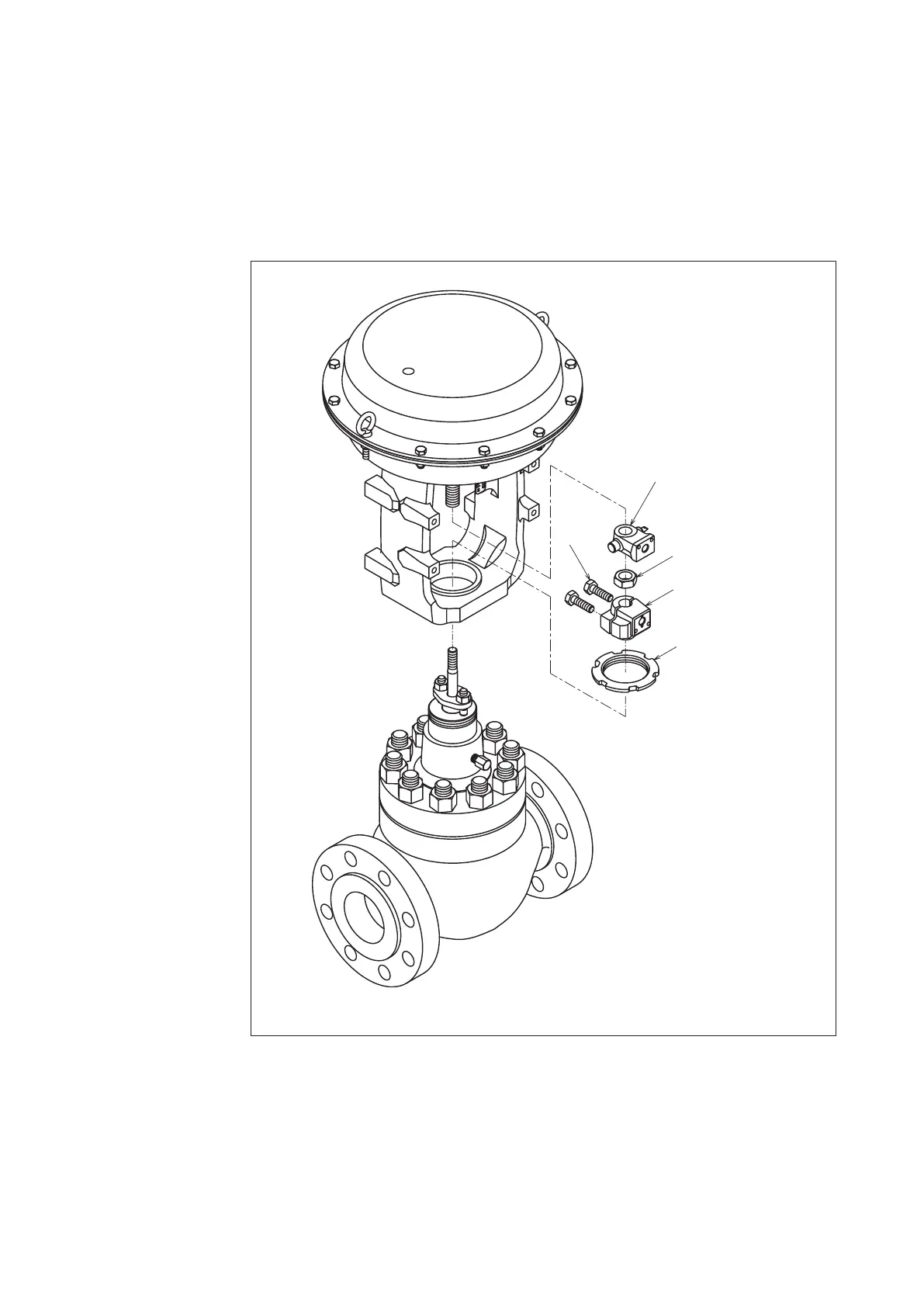
Figure 4-7
When disassembling or assembling the actuator, keep it in the vertical attitude. For the
tightening torques of bolts and nuts, see Table 4-4, Table 4-5.
For the names of the parts, see Figure 4-13 and Figure 4-21.
Pointer
Hex Bolt
Lock Nut
Stem Connector
Yok
 Loading...


