4-35
Assembling actuator
<Cautions during assembly>
Refer to the chapter of inspection items during disassembly and verify that no abnormality
is found on the parts. If any are found, replace or repair as required.
The O-ring of sliding parts should always be replaced at the time of periodic disassembly.
Whenever the O-ring on the fixed part is deformed, damaged, or scarred during
disassembly, replace it.
Clean the O-ring, oil seal, wearing, and tape liner O-ring recess and apply sufficient of
lubricant.
Ensure that no dust or dirt from maintenance work prior to reassembly remains on sliding
part of cylinder and guide bushing.
Assembly of actuator with manual handwheel
See Figure 4-23 and Figure 4-24 for assembly on part names.
1. Assembly of manual handwheel and cylinder assembly
Step Procedure
1 While yoke No.23 is in upright position, place gear case No.28 and temporaily
fasten it with hex head bolts No.9 (four).
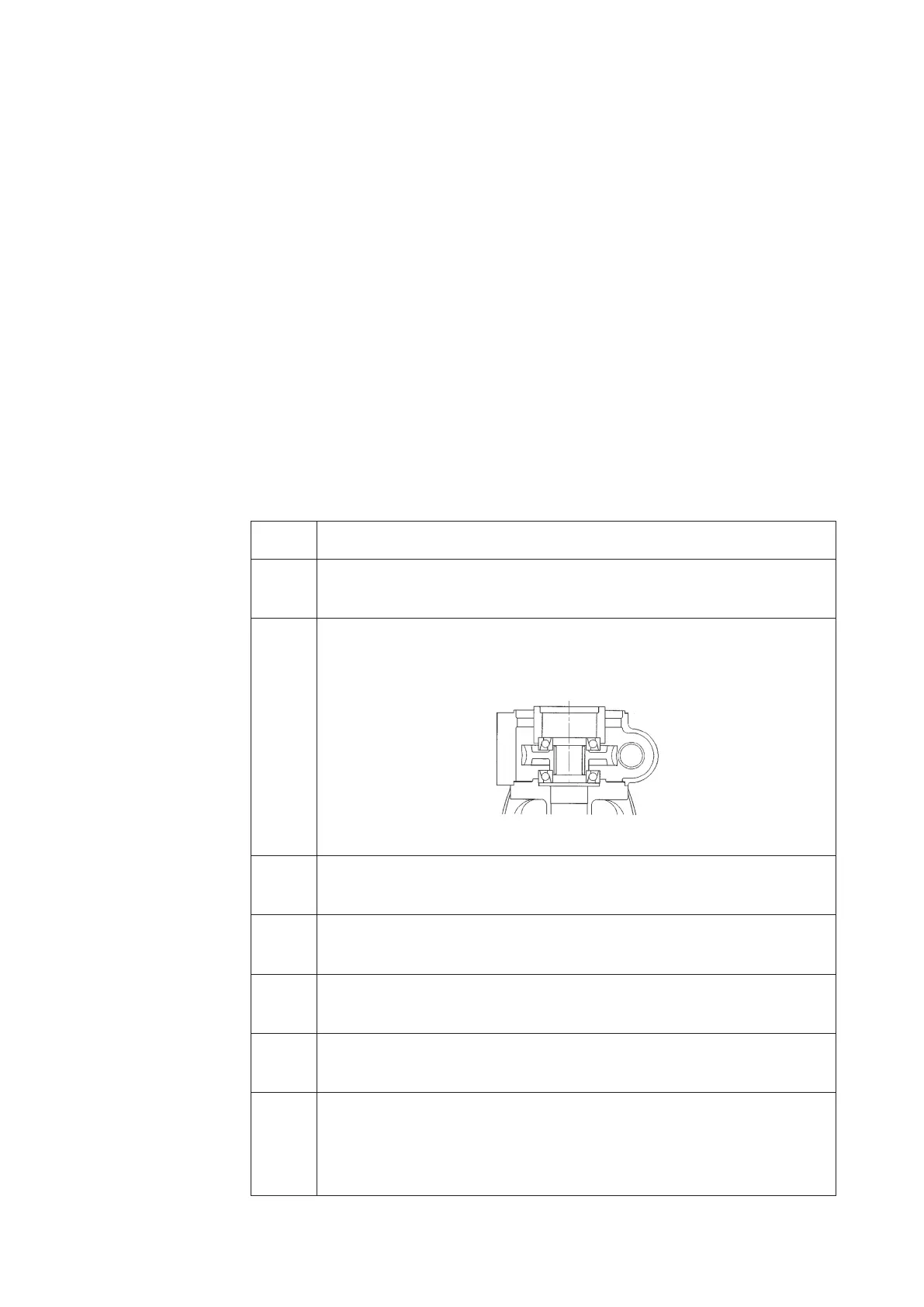
2 Apply lubricant on the single column angular bearing (top and bottom) and
assemble in sequential order the bearing (lower) No.30, worm wheel No.31,
Bearing (upper) No.30 and bearing holder No.29. See Figure 4-29 below.
Figure 4-29
3 Insert and screw in from the bottom slide screw No.32 assembled with wear ring
No.14. Apply Inbricant on the threaded parts of slide screw No.32.
4 Assemble slide screw No.32 with slide screw rotation stpper No.36, hex head bolt
No.50 and nut No.51.
5 Apply lubricant on rod packing No.15 and dust seal No.17 and assemble them
into cylinder No.14.
6 Place cylinder No.14 on gear case No.28 and temporarily fasten it with hex head
bolts No.6 (four) and seal washer No.7.
7 Use rod No.1 to set the position of the cylinder by ensuring that the rod moves
smoothly and the tighten with the torque given on Table 4-5. If the rod does not
move smootyly, tap the cylinder or gear case gently with plastic hammer and set
the position.
 Loading...


