Inspection and Maintenance of Control Valves Azbil Corporation
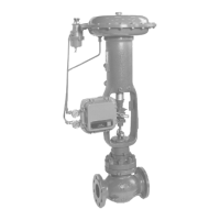
3-2 VDC, VAC, VST, VAA - Diaphragm Control Valve
• Check that there are no loose bolts on the stem connector which connects the
actuator stem to the valve stem.
• Check that the actuator stem and valve stem are not warped and show no sign of
damage.
• Check that valve operation is smooth and valve lift is correct
• Check that the control valve does not generate any abnormal sound or vibration.
• Check that there is no leak from the gland packing section. If the control valve
has a lubricator, periodically lubricate and tighten the gland packing section.
• If the Control valve has a manual handwheel, check that the pointer of the
operation nut conforms with the AUTO position and that the handwheel is locked.
3-3 : Lubrication of Gland Packing (for valve with asbestos packing)
(See Figure.3-1)
For a valve which employs asbestos packing, a lubricator is supplied being mounted
on the bonnet. For lubrication, be sure to use the correct type of lubricant grease as
indicated on the nameplate. (If the valve is with V-teon or a similar type of gland
packing which requires no lubrication, the column for grease on the nameplate is
blank).
To lubricate gland packing, proceed as follows: Fill the lubricator with fresh grease.
Loosen the lubricator handwheel and then squeeze grease into the gland packing
by turning the squeezer screw. If gland packing cannot be fully lubricated even
when the squeezer handle is inserted as far as it goes, tightly close the lubricator
handwheel, retract and take out the squeezer screw, ll the lubricator with fresh
grease once more, squeeze grease into the gland packing by setting and turning
the squeezer screw, and then fully close the lubricator handwheel. Repeat this
procedure until gland packing is fully lubricated with grease.
Be sure to securely tighten the lubricator handwheel when the lubrication work is
nished. It is recommended to tighten slightly more the packing ange bolt slightly
more after lubrication work is nished.
Figure 3-1 Lubricator

 Loading...