Safety Guide Azbil Corporation
viii Model MTG11A/18A, MTG11B/18B, MTG14C
5 : Caution on disassembly and reassembly
5-1 : Disassembly
CATUTION
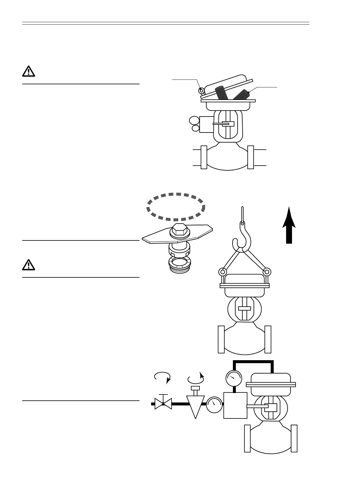
• When disassembling a spring-
incorporated positioner, follow the
prescribed procedure in removing
bolts and nuts. Otherwise, the spring
may pop out and could resulting in
physical injury.
• When the eye-bolts of actuator are
used to lift the valve from the pipe,
ensure that the weight limit given
in manual is adhered to. Otherwise,
there is the danger of dropping the
valve,
• When removing the trim (inner
valve) from the body, ensure that
the proper type of specialized tool is
used. Refer to the instruction manual
for the tools that should be used.
Otherwise, the trim may be damaged.
Y
HTS
2-inch
Specialized
tool
Weight
limit
Y
Stop
valve
Reducing
valve
Close Open
WARNING
• Before disassembling the valve,
ensure that the pressure within piping
has been reduced to atmospheric
pressure. Flow out of process uid
may cause physical injury.
• When disassembling the valve,
ush out the interior of the valve
or replace the uid inside. Residual
process uid may cause physical
injury,
• Do not disassemble the pneumatic
actuator with supply air on.
Compressed air may cause physical
injury.