Additional programming: Industrial analog and industrial pulse Page 12/20
OG_IOG_BA_02_1401
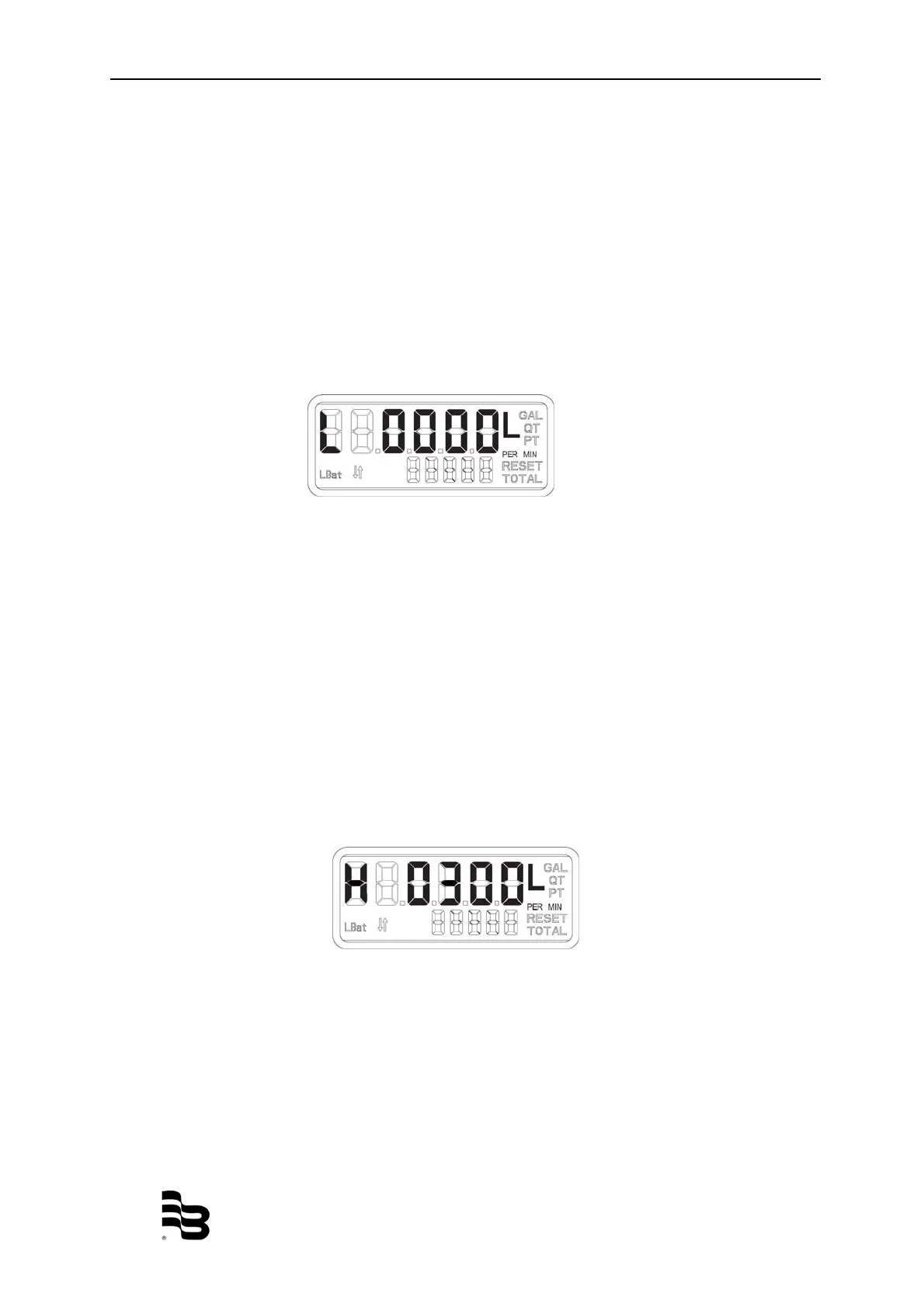
9.2 Analog minimum flow rate
(for models ILR 730 only)
Indicated by a “L” on the left hand side of the display, this screen allows the setting of
the flow rate that corresponds to the 4mA output:
NOTE: The minimum flow rate value must be less that the maximum flow rate value.
• Minimum 0.0 LPM/GPM
• Maximum 100.0 LPM/GPM
• Default 0.0 LPM/GPM
NOTE: Error checking will not allow the user to advance to the next screen.
To advance to the next programming screen, hold the TOTAL button for one second.
9.3 Analog maximum flow rate
(for models ILR 730 only)
Indicated by a “H” on the left hand side of the display, this screen allows the setting of
the flow rate that corresponds to the 20mA output:
NOTE: The maximum flow rate value must be greater than the minimum flow rate
value.
• Minimum 0.0 LPM/GPM
• Maximum 100.0 LPM/GPM
• Default 30 LPM / 8 GPM
To advance to the next programming screen, hold the TOTAL button.
NOTE: Error checking will not allow the user to advance to the next screen.
Figure 11: Analog minimum flow rate screen
Figure 12: Analog maximum flow rate screen
 Loading...


