INTERNAL EXTERNAL
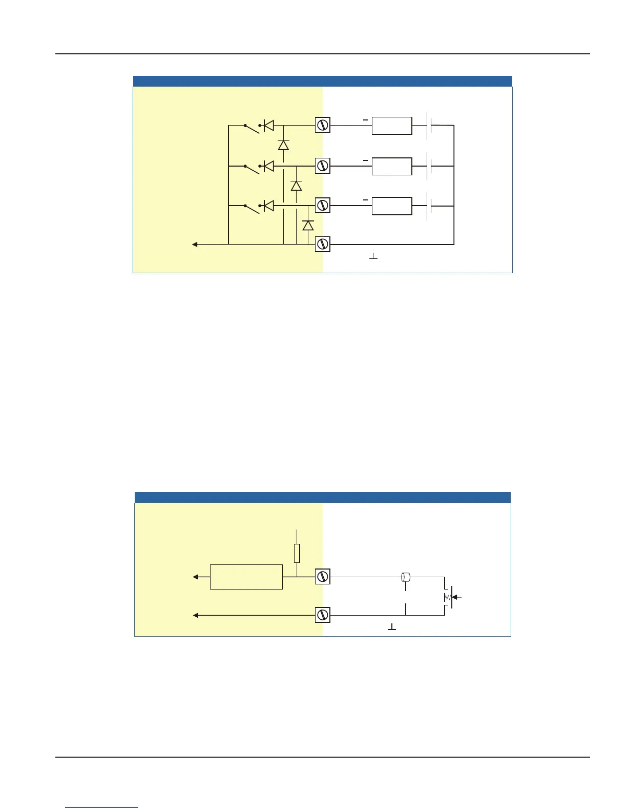
Passive transistor outputs - T1, T2 and T3
+
14
13
T1
Maximum
50V DC - 300mA
Common ground unit
- GND
DEVICE
+
15
T2
DEVICE
+
16
T3
DEVICE
Figure 14: Passive transistor outputs T1, T2 and T3
Terminal #22-24; 80…230V AC power supply:
Connect AC power only after all other wiring has been completed.
The PC200 has an internally mounted line filter and fuse for surge protection. The unit is designed to operate with
85…265V AC power or DC voltages (see terminal #27-28).
Always make sure to connect terminal #24 to the electrical system ground.
Terminal #27-28; 24V DC power supply:
Use these terminals ONLY for DC-operated applications. The supply must be a 24V DC +10%.
For AC applications, use terminals 22-24.
Terminal #30; Reset cycle counter:
Use the RESET CYCLE COUNTER function for end-of-shift coordination and control. The inventory cycle counter can be reset to
zero. The input must be switched with a potential-free contact to the GND terminal #01 or #08 for at least 100 msec.
You can also use terminal #30 to block the RESET function from the keyboard: as long as this input is switched to terminal #1
or #08, it is not possible to clear the actual counter. You must first release the input to clear the COUNT value.
INTERNAL EXTERNAL
External RESET CYCLE COUNTER input
30
Common ground unit
SIGNAL
1 or 8
GND
shielding
RESET
CYCLE
COUNTER
SWITCH
+ 3.2V DC
1M
low-pass lter
Figure 15: External reset cycle counter input
Terminal #42-44; control output R1:
Use the mechanical relay CONTROL OUTPUT R1 to control the batch process. Relay 1 is switched ON during the whole batch
process. The maximum switch power is 240V-3A per output.
User Manual
Page 15 April 2017 CTL-UM-00483-EN-07