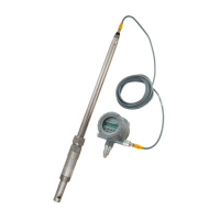
Installing a VN2000 Meter
Page 9 June 2018 VRX-UM-02217-EN-04
Installation Procedure
The hot-tap method involves inserting the flow meter through a full port valve and requires greater clearance space for
removal and installation.
OTE:N For pipes under pressure, use the Insertion/Extraction Tool. See “Using the Optional Insertion/Extraction Tool” on
page11.
The flow meter is shipped completely assembled, tested and ready to install and operate in its permanent location. These
instructions assume the pipe has been fitted with a 1-1/2 in. hole, a Weldolet®, nipple and valve. The valve must be threaded
full bore.
When the flange version is used, a flange is supplied. This flange has an overall height of 3 in. This must be taken into account
when installing the nipple.
MPORTANTI
There is a sensor mounted on the end of the insertion probe. Do not stand the meter on its end. Be careful not to hit or push this end,
or damage to the sensor may occur.
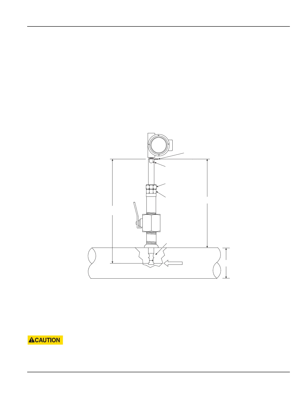
FLOW
30 in.
(762 mm)
A
Arrow must point
downstream in
direction of ow.
Large hex nut secures
the bar in place.
Small machined
hex nut tightens
meter into the valve.
H
Alignment ag
Sensing element
Figure 3: Calculate insertion depth
The probe must be inserted until the shedder bar in the sensing element is at the midpoint of the pipe.
1. Calculate the required insertion depth of the vortex meter by dividing the pipe diameter (H) by 2.
2. Calculate how far the alignment ag at the top of the insertion shaft should be from the outside of the pipe wall, for
proper insertion depth: A = 30 inch – (1/2 * H)
3. Fully retract the probe until the insertion end is within the sealing unit.
4. Hand-tighten the large hex nut to hold the meter shaft in place during installation.
THE NUT IS NOT A SEALING NUT. THE NUT IS ONLY DESIGNED TO HOLD THE BAR IN PLACE DURING PRESSURIZED
APPLICATIONS. DO NOT OVER TIGHTEN THE NUT BECAUSE GALLING WILL OCCUR. TIGHTEN THE NUT BY HAND, THEN
TIGHTEN WITH A 24 IN. WRENCH AFTER THE BAR IS INSERTED TO THE DESIRED INSERTION DEPTH.