Using the Optional Insertion/Extraction Tool
Page 13 June 2018 VRX-UM-02217-EN-04
Using the Tool to Remove a Meter
BURN HAZARD. THE PROBE MAY BE HOT TO THE TOUCH IF THE FLUID IS HOT.
Attach the tool to the insertion meter:
1. Holding the back of the tool, place the tool behind the meter with the bottom (larger) clamp assembly in line with the
meter’s seal assembly.
2. Place the clamp cradles, with the bottom (larger) clamp assembly around the meter’s seal assembly, just below the
machined step on the seal, and the upper (smaller) clamp assembly around the meter shaft, 2 in. down from the top of
the shaft.
3. Secure the tops of the clamp assemblies to the cradles with the bolts provided.
MPORTANTI
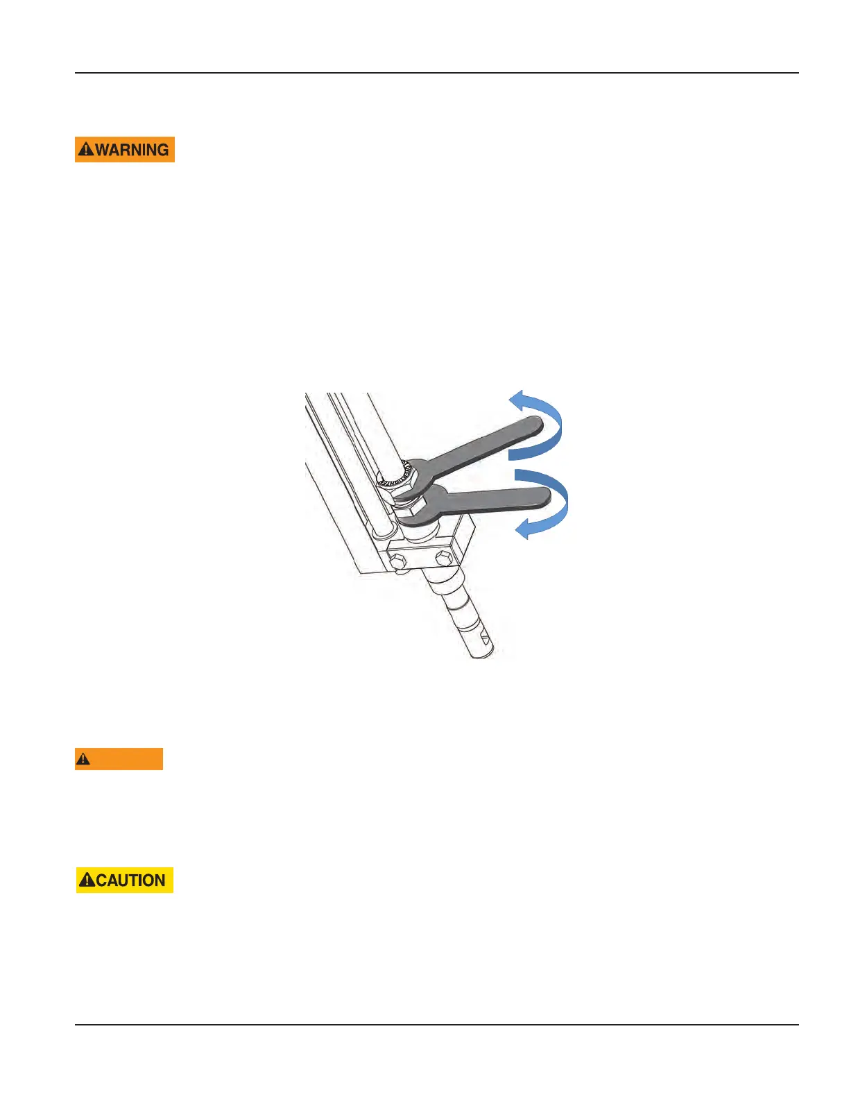
To make sure the seal assembly does not turn while the large hex nut is loosened, use two wrenches. Turn the wrench on the seal
assembly clockwise as you turn the wrench on the hex nut counterclockwise.
Figure 6: Removing the hex nut
4. Loosen the large hex nut and split ring (you may have to tap the nut with a hammer to free the split ring).
5. Completely back off the hex nut from the threads.
WTRNING
AFTER THE NUT IS COMPLETELY REMOVED, THE PRESSURE IS AGAINST THE INSERTION TOOL. DO NOT STAND IN THE
DIRECTION OF EXTRACTION AS PERSONAL INJURY COULD OCCUR.
7. Attach a wrench or a 1-1/8 in. socket wrench to the top of the threaded spindle of the insertion tool and turn the spindle
until the sensing element is extracted from the pipe and retracted up into the seal assembly.
MAKE SURE THE METER IS WELL PAST THE VALVE AND INTO THE SEAL ASSEMBLY BEFORE TRYING TO CLOSE
THE VALVE. IF FLOW METER SENSOR IS STILL IN THE VALVE WHILE IT IS BEING CLOSED, DAMAGE CAN OCCUR TO THE
SENSOR ELEMENT.
8. Close and purge the valve.
9. Remove the seal assembly slowly. There may be an amount of pressurized uid in the nipple, or the valve may not be
sealing properly.