Introduction
Page 7 June 2018 VRX-UM-02217-EN-04
INTRODUCTION
The VN2000 Hot Tap Insertion Vortex Flow Meter measures the volumetric flow rate, mass flow rate or BTU/energy of
steam, gas or liquids over a large flow range. The meter is a heavy duty design engineered to stand up to the most abusive
environments inside and outside the pipe.
Principles of Operation
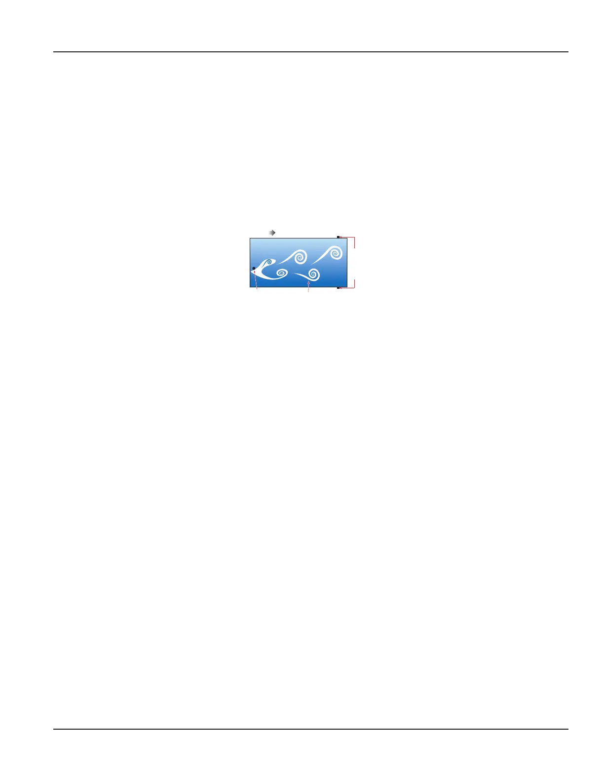
An everyday example of a vortex shedding phenomenon is a flag waving in the breeze: the flag waves due to the vortices
shed by air moving across the flagpole. Within the flow meter, as flowing fluid moves across the tiny strut or “bluff bar”,
vortices are shed on a smaller scale. The frequency of the vortices shedding is proportional to the fluid velocity.
Through the use of an internal RTD, the flow meter software compensates for changes in temperature, to achieve an accurate
mass flow measurement.
FLOW
Small Strut
Shed Vortices
Dual
Piezo-
electric
Sensors
Figure 2: Vortex shedding
Sensor Operation
Two piezoelectric pressure-sensing crystals are mounted internally in the insertion vortex meter in proximity to the
vortex-generating element, called the shedder bar. Two sensors sense the vortex signals. The crystals convert the pressure
pulses created by the vortices into voltage signals without the need of excitation current or voltage. The sensor crystals are
never in contact with the fluid. The piezo crystals are encapsulated in a stainless steel module.
Calibration Factor
The frequency at which vortices are shed is a linear function of fluid velocity, and therefore, a measure of flow. In the range
covered by the particular flowmeter, vortex frequency is insensitive to specific gravity, viscosity, and temperature of the fluid,
and depends only upon the width (d) in inches and shape of the flow element, and the inside diameter (D) of the pipeline
in inches.
The frequency is F = SV/d
Where:
F = Karman vortex frequency
S = constant (Strouhal Number)
V = fluid velocity at the flow element
D = face width of the element