20 | 36W. Baelz & Sohn GmbH & Co. · Koepffstrasse 5 · 74076 Heilbronn · Germany · www.baelz.de Seite | Page
Motorized Linear Actuator baelz 373-E45
8.2.4 Normal and safety modes
Innormalmodethepositionofthevalveiscontrolledbytheset
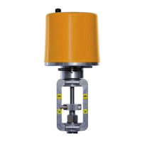
valueatanalogueinputAI2.TheN↔Sswitchshowninthepicture
ontherightissettonormalmode(N).Innormalmode,noexternal
controlsystemscanbeconnectedtoterminals12and14.
8.2.4.1 Safety mode: freeze protection and excessive temperature
Insafetymodetheactuatorcanbesenttoasafeposition(extended/retracted,dependingon
thedirectionofactionofthevalve)incaseoffailureormalfunctioningofthemicrocontroller.
TooperatetheBaelz7020Ainconnectionwithanexternalfreezeprotectionand/orexcessive
temperaturethermostat,settheN↔Sswitchtosafetymode(S).
Connectthefreezeprotectionand/orexcessivetemperaturethermostataccordingtodesired
functionandpriority.Besuretotakethedirectionofactionintoaccount!Seewiringdiagrams
inthebaelz7020operatinginstructions.
8.2.5 3-point control with a continuous output signal
1. Setthepositionerupandwiretopowersupplyasdescribed
previouslyandinitializeasdescribedinsection8.5.2.
2. Todeactivatetheerrorsignal,ifdesired,settheDIP-switch11to1
("ON")andchangethefollowingvaluesinthemenuitem"CA"using
WinBasTools(onPC,seebaelz7020operatinginstructions
):
● AD to 0
● EFPto0.0%
● LA to 1
(Ifyoudon'tmindtheredLEDerrorsignal,step2canbeleftout
completely.Thishasnoeffectonthefunctionofthepositioner.)
3. SettheN↔Sswitch(Fig.6
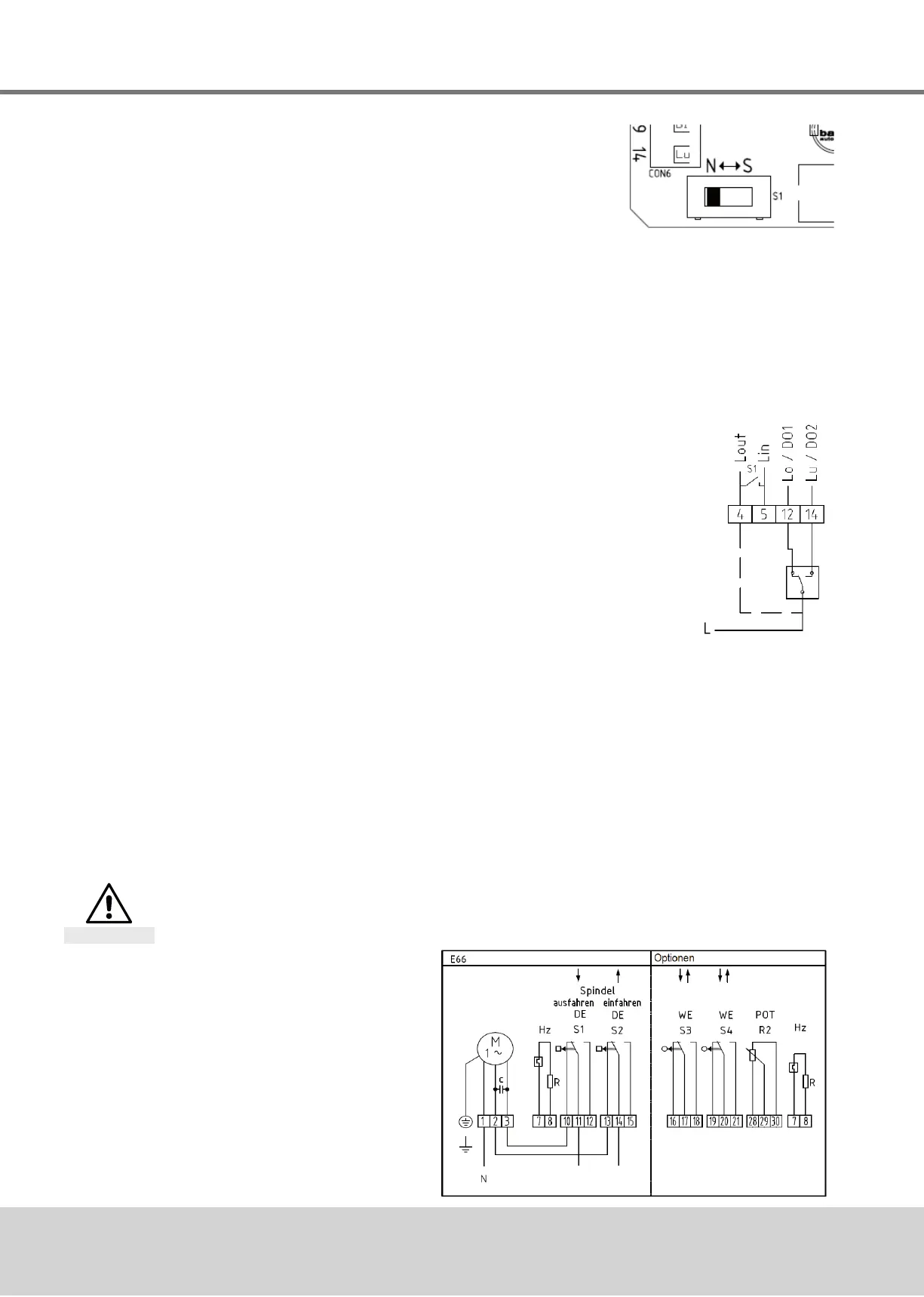
)to"S"andwireasshowninFig.7(thepositionermust
remainconnectedtothepowersupplythroughout).
4. TherequiredsignalcannowbepickeduponAO1andAO2.
IMPORTANT NOTE:Beforeanyfurtherre-initializationofthedevice,disconnectterminals12
and14andsettheN↔Sswitchtonormaloperation(N).
8.3 Wiring diagrams and allocation of connection terminals
Disconnect actuator from power supply before starting work
See also section 4.4.
Danger
8.3.1 Wiring diagram
Fig. 6: N↔S-switch
Fig. 7: Wiring diagram
3-point-signal
Fig. 8: Wiring diagram
basic actuator